Equipment
Raspberry Pi Fermentation Temp Controller III: Server APIs
This is the optional part of the Raspberry Pi Fermentation Controller, but it’s the part that I used to roll into the Brewery IoT page.
There are three PHP scripts that run on the server:
- Index.php – collects data
- getRows.php – lists data from the database
- getLast.php – gets the last temperature entered in the database
There are also two prerequisites:
- A pre-shared .pem key on the server. This should match the one on the Raspberry Pi.
- A MySQL table (I’ve called it FermChamber, but if you know SQL, you can change it) with two columns: TimeStamp (datetime) and Temp (float).
With that out of the way…
Index.php – Data Collection
The data collection script is below. It expects post form data with a JSON formatted file. If you’ve followed the first post in this series, you’re good.
Note that you will need to change the code to use your correct server, username, password, and database.
getRows.php – List of Data (for the bar graph)
This script gets the temperatures in the database for the line chart.
getLast.php – Get Last Temperature Reading
This is just a simple script to get the last temperature in the database. This is for display on the dial gauge.
One of the next parts in this will be the code to display on the page.
Cheers!
Raspberry Pi Fermentation Controller II: Power
I started on building a Raspberry Pi based fermentation controller. This is a device that turns my chest freezer on and off based on the temperature of the freezer and what the Raspberry Pi thinks (which is essentially what I programmed it to do).
This is one of those posts that gets a disclaimer: BE CAREFUL IF YOU DO SOMETHING LIKE THIS. You can get killed by touching the wrong thing here, and it will hurt then entire time you’re dying. People will not be able to see your bones as you flash from electrocution. Marv wouldn’t have lived. I’m not an expert or licensed or even qualified to do this (and since I’m doing this, does that make me a Redneck)? Your mileage may vary, of course.
There are really only two major parts to this, a solid-state relay (SSR) and an outlet. I removed the little tab connecting the two hot-sides of the outlet together to allow for one to be on always and the other to be on just when the SSR says it should be. This is all wired to a plug (I used an old computer cord that was conveniently colored on the inside. A diagram of the connections is below.
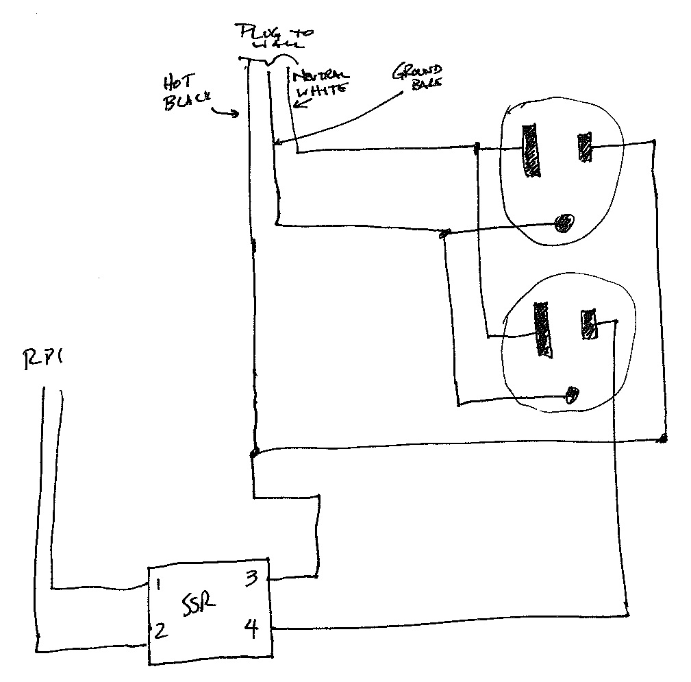
Wiring diagram. Not to scale. Don’t trust the numbers on the SSR – they’re from memory.
Some notes:
- This should not be hard-wired into the electrical system. It is probably code to have things like this be easily able to be disconnected, and the plug allows for that. Also, intelligence dictates that things like this should be able to be unplugged should some failure happen down the line (and since electricity is involved, those failures can be spectacular and bright… and deadly).
- One could make the case for needing a fuse in this. I don’t think it needs one. However, this is protected by both a circuit breaker (as is everything in the house) and a GFCI (because the plug it will use is near a sink). I’m truthfully not concerned, but I don’t know if I’m right to be unconcerned.
- Solid state relays should ALWAYS have heat sinks, and thermal grease between the sink and the SSR.
- SSRs are rated. It needs to be able to handle at least enough current as the freezer, although I recommend double. My freezer claims 2.5 amps, my SSR is 40 amps. Should be safe.
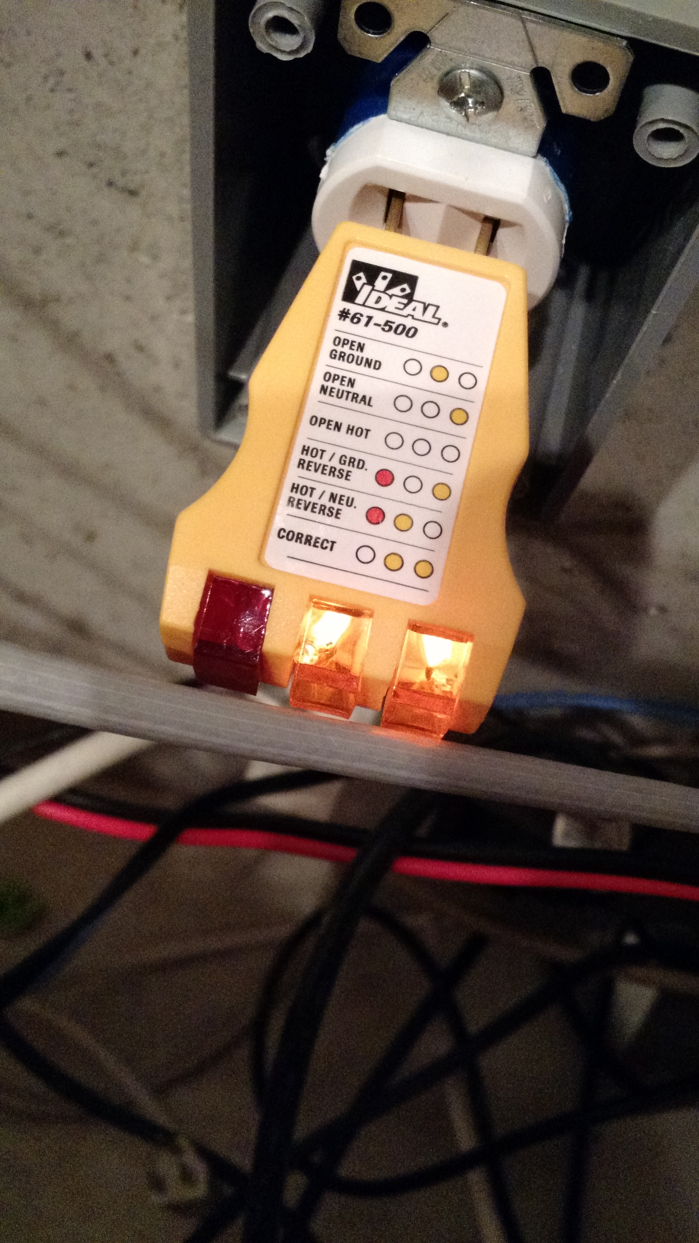
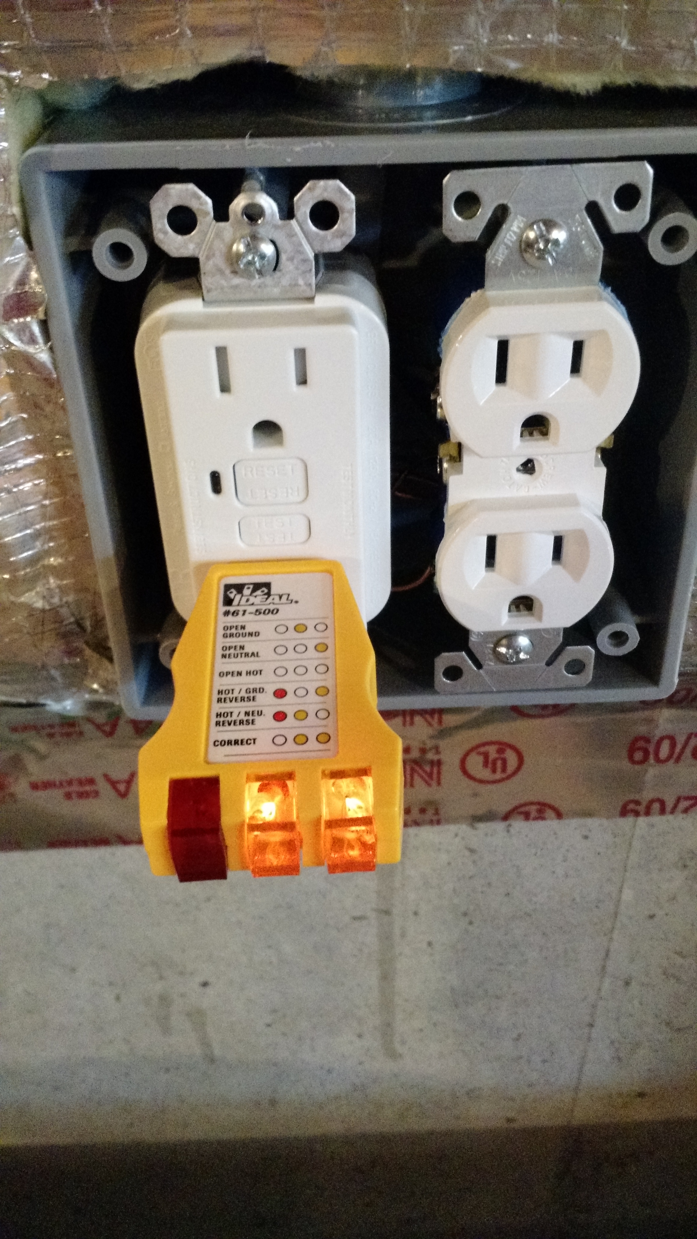
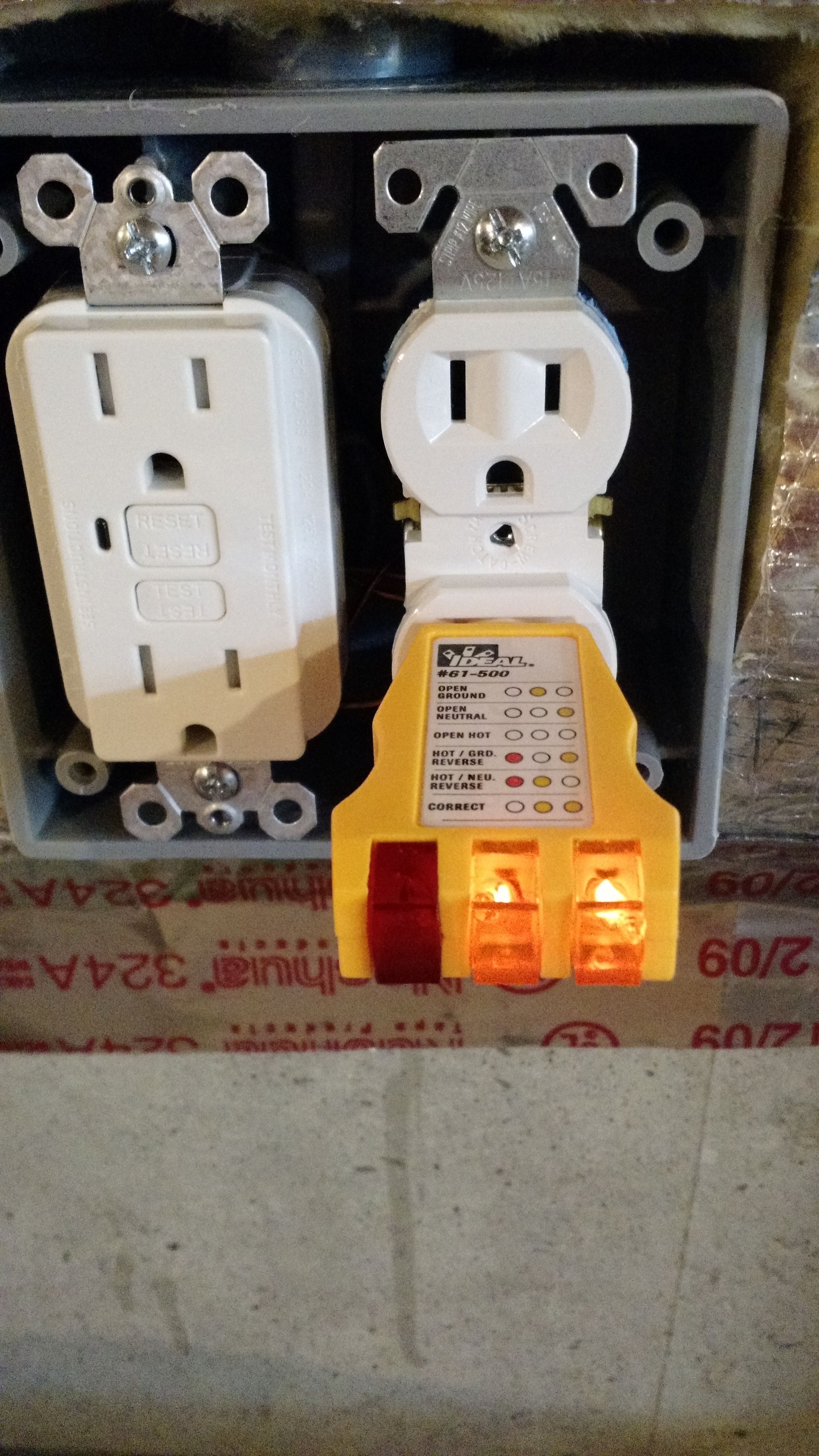
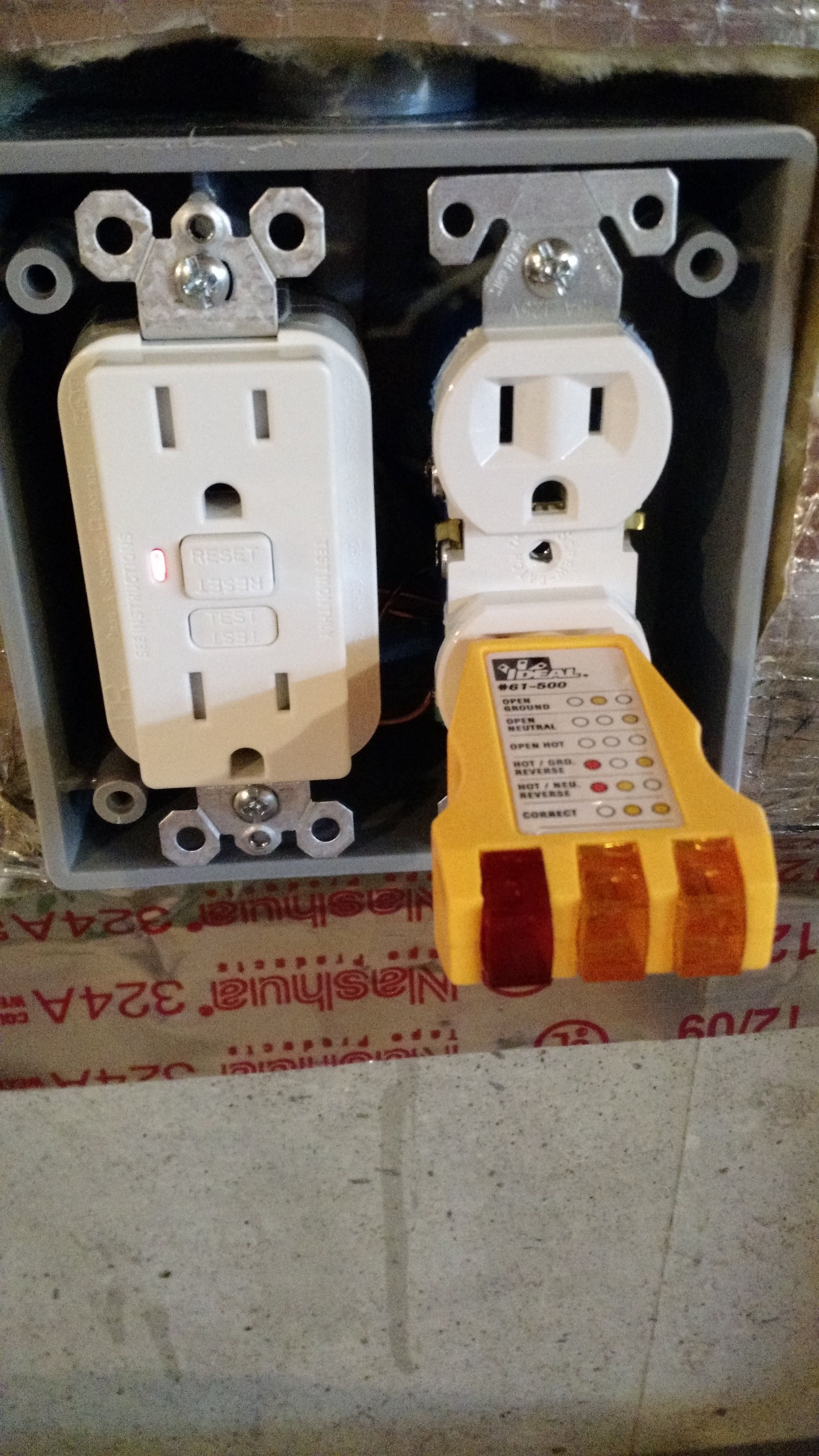
- Test everything using a safe tester and test method. For outlets, the $5 3-prong tester like I use is adequate and safe – much much safer than a multimeter. Truthfully, every homeowner should have one of these (and when my house was built, I used this little tester on every single outlet).
- Everything should be in a box, in case something happens. Said box should be waterproof as much as reasonably possible.
Pictures are below.
-
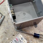
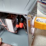
- Near beginning. Added an outlet to the side.
-
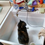
- My cat, Mocha, wants me to brew a mocha stout, I guess.
-
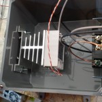
- Solid-State Relay in place.
-
- Testing. This is a more dangerous part because I don’t have the covers in place.
-
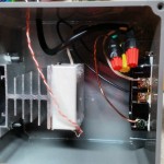
- Internal finished view.
-
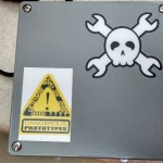
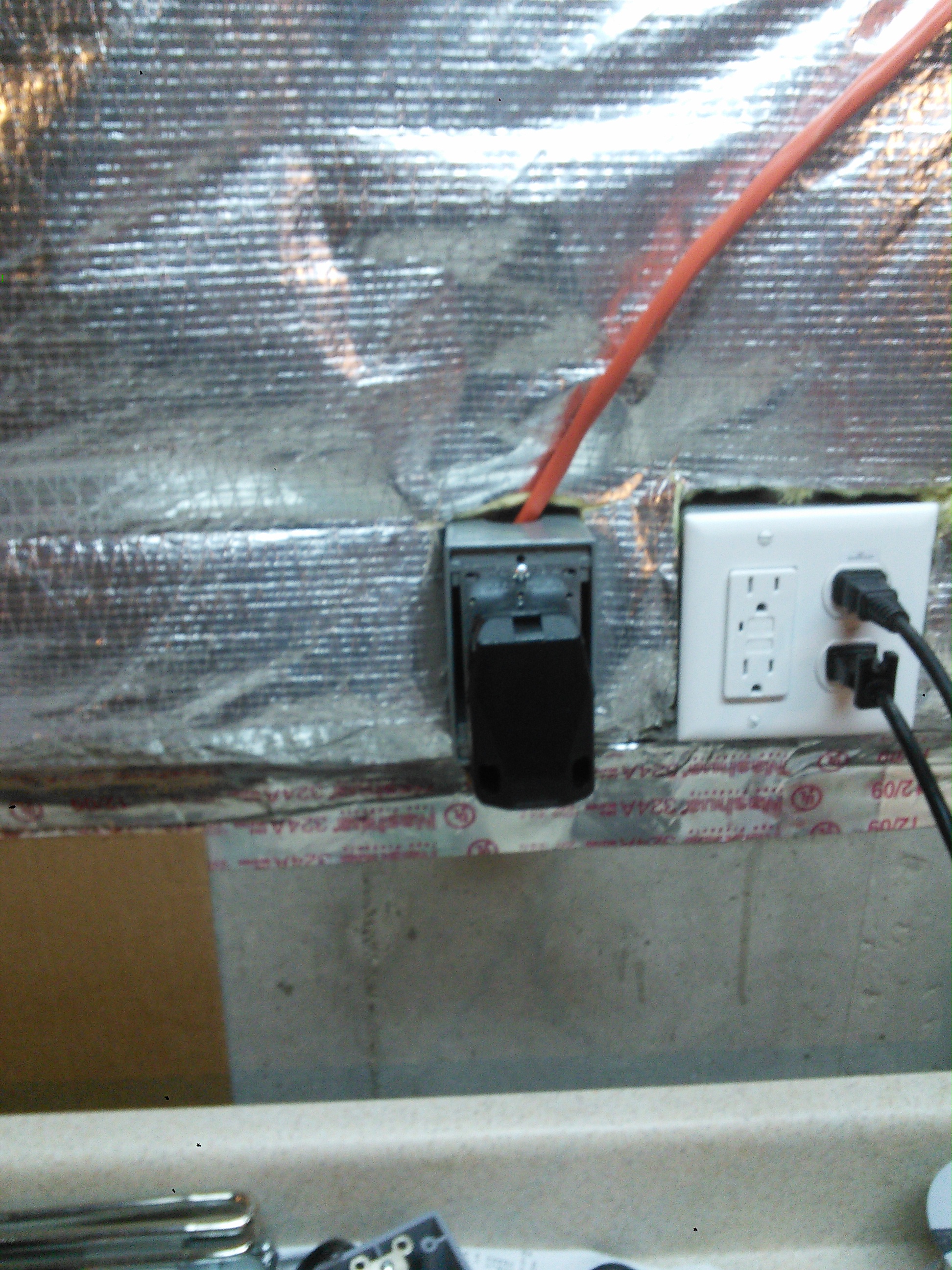
- External finished. Complete with some stickers!
-
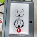
- Side. The lower outlet is on the relay, the upper outlet is always on.
The only problem I ran into was that the $3 Chinese solid-state relay is bad. The switched outlet is on regardless of the input (although I’m still testing things, so not 100% sure if I’m right, but I’m ordering like 3 more… after all, they’re like $3 and out of the last two I purchased, one is probably bad). I’ve tested (with the unit unplugged) across the SSR terminals and did not find a short, and across the two hot sides of the receptacle and did not find a short. But in the case of the SSR, it may not display a short to my tester because it is a much lower voltage than the outlet.
EDIT
The relay was probably fine. It appears that there is a minimum current required to turn on/off the SSR, and the 1/4 watt tester was not enough of a load. I replaced the relay (with one of the FIVE I bought), and plugged the freezer into it, despite the new one showing the same signs as the old one. The freezer did not turn on when I powered-on the Raspberry Pi (I had turned it off to plug it into the box’s unswitched outlet). I made a quick administrative code edit, and it worked.
Cheers!
Raspberry Pi Fermentation Temp Controller I: cron jobs 1 and 2
This is the first of a handful of posts about getting my fermentation temperature controller up and running. As I indicated before, there are three python scripts on the Raspberry Pi that make this all work.
For those that don’t know, the Raspberry Pi is a small computer that is about the footprint of a credit card. It isn’t very powerful, but you don’t need power to do this temperature control. One thing you DO need for this is called GPIO, or General Purpose Input/Output. These can be used as switches in code. There are many ways to use these, but the easiest (in my opinion) is using Python.
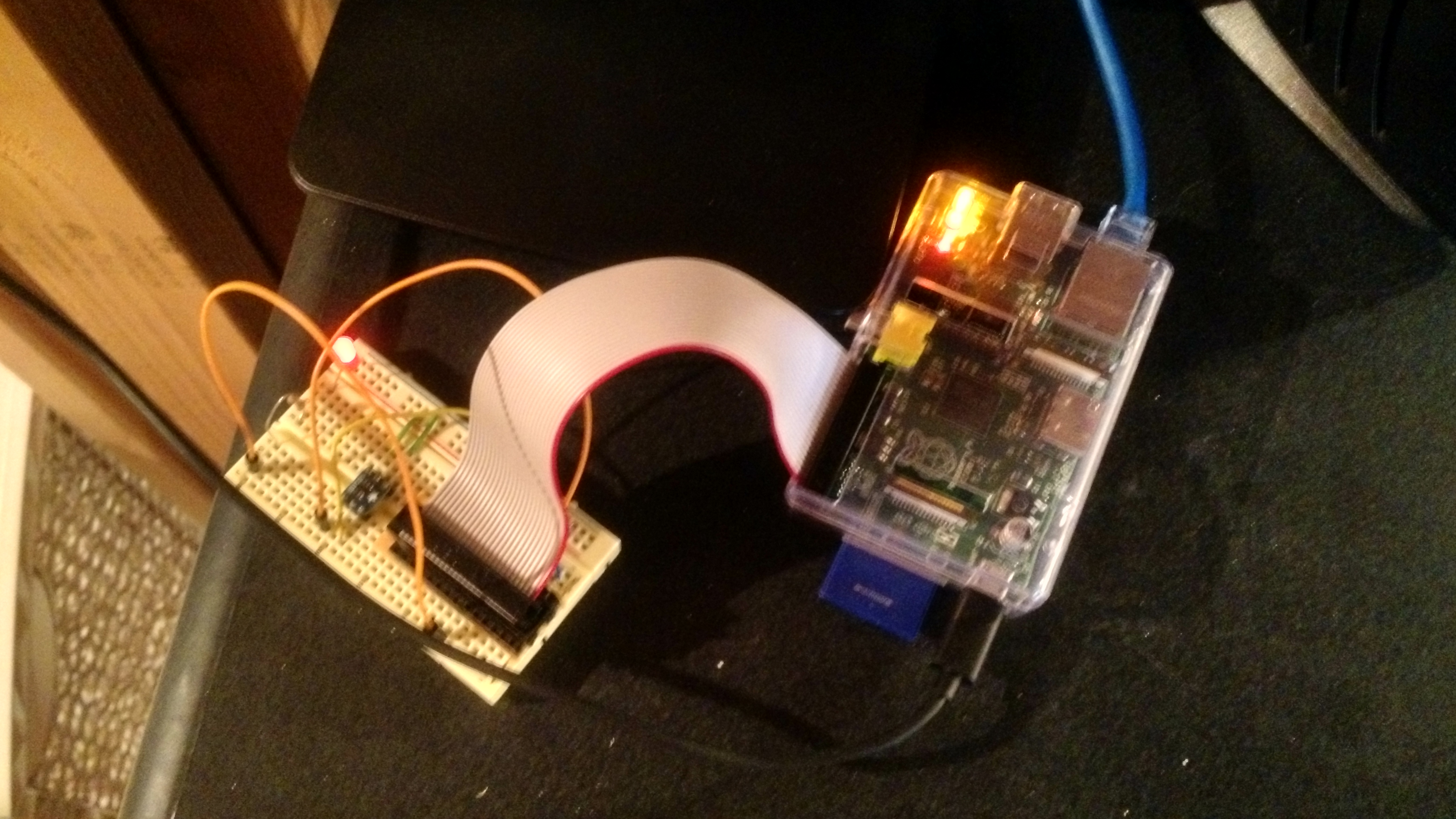
Raspberry Pi connected to a breadboard.
My current setup is with the Raspberry Pi connected to a breadboard, which is a device that allows solder-free connections (solder is somewhat permanent and soldering parts to a PCB is a lot of work). In the image above, the ribbon cable connects to all the GPIO pins on the Raspberry Pi, and specific pins are being used to connect to a temperature sensor and to a light emitting diode (LED).
The two parts of code are to check the temperature and determine if the temperature has gone too low (the Emergency Stop Script), and the other is to send the temperature to a server (the API Send Script).
Emergency Stop Script
This is the check script. It checks the temperature and shuts off the GPIO output if the temperature is at or below 32. Two things to note on this, one is that if this temperature sensor is just in the chamber, the beer will probably be a degree or two warmer (unless it stays at 32 for a while). The other thing to note is that if you are making eisbock, you should probably change or disable this script.
The script above should be set in the cron manager (crontab -e) to run every minute:
*/1 * * * * sudo python /home/pi/source/pyTemp/pyECheck.py > /home/pi/source/pyTemp/pyECheck.log
The code above has it run every minute (the */1). The path to the script on my Raspberry Pi is /home/pi/source/pyTemp/pyECheck.py, and the output log file is /home/pi/source/pyTemp/pyECheck.log. Note the use of sudo on this script – or “superuser do”. This runs the script as a fully privileged user, which is required to use the GPIO pins.
API Send Script
This is the script to send the data to a server. There are a few things that need to be changed. One is that you need to generate an encryption key that will be used on the Raspberry Pi and the web server to encrypt and decrypt the data. This is almost overkill, but it ensures that it cannot be screwed with. The other thing that needs to be changed is the server address. These are both at the top of the file.
This script should not be run every minute (that’s what we’d call overkill). I use every 10 minutes, although it could be less often.
*/10 * * * * sudo python /home/pi/source/pyTemp/pyTemp.py > /home/pi/source/pyTemp/pyTemp.log
The next part of this will be either the actual Raspberry Pi connections or the PHP server backend. But either way, likely both are coming within the next few weeks although regular programming may be interrupted by a brew day report.
Cheers!
Dangerous Electric Boil Kettle DONE!
I had some free time over the weekend and was able to work on the brew kettle. As of Saturday afternoon, I was boiling water and if it wasn’t for having a few things to do I would have probably ran over to my LHBS and got a few pounds of malt and hops.
The things I did dangerously was that I used all green wire (the standard AC convention is red or black for hot, white for neutral, and green for ground). Also, I have no enclosure around all that power. I also do not have a way to disconnect this from power (other than a breaker, which is currently switched off since I’m not brewing anything).
While I was at it, I replaced my valve with a non-leaking valve (my previous valve was actually for a compression fitting, so it leaked). There is a remaining issue – I have to replace the fitting on the thermocouple because right now I have a compression nut (which leaves a place for bacteria to sit and harvest).
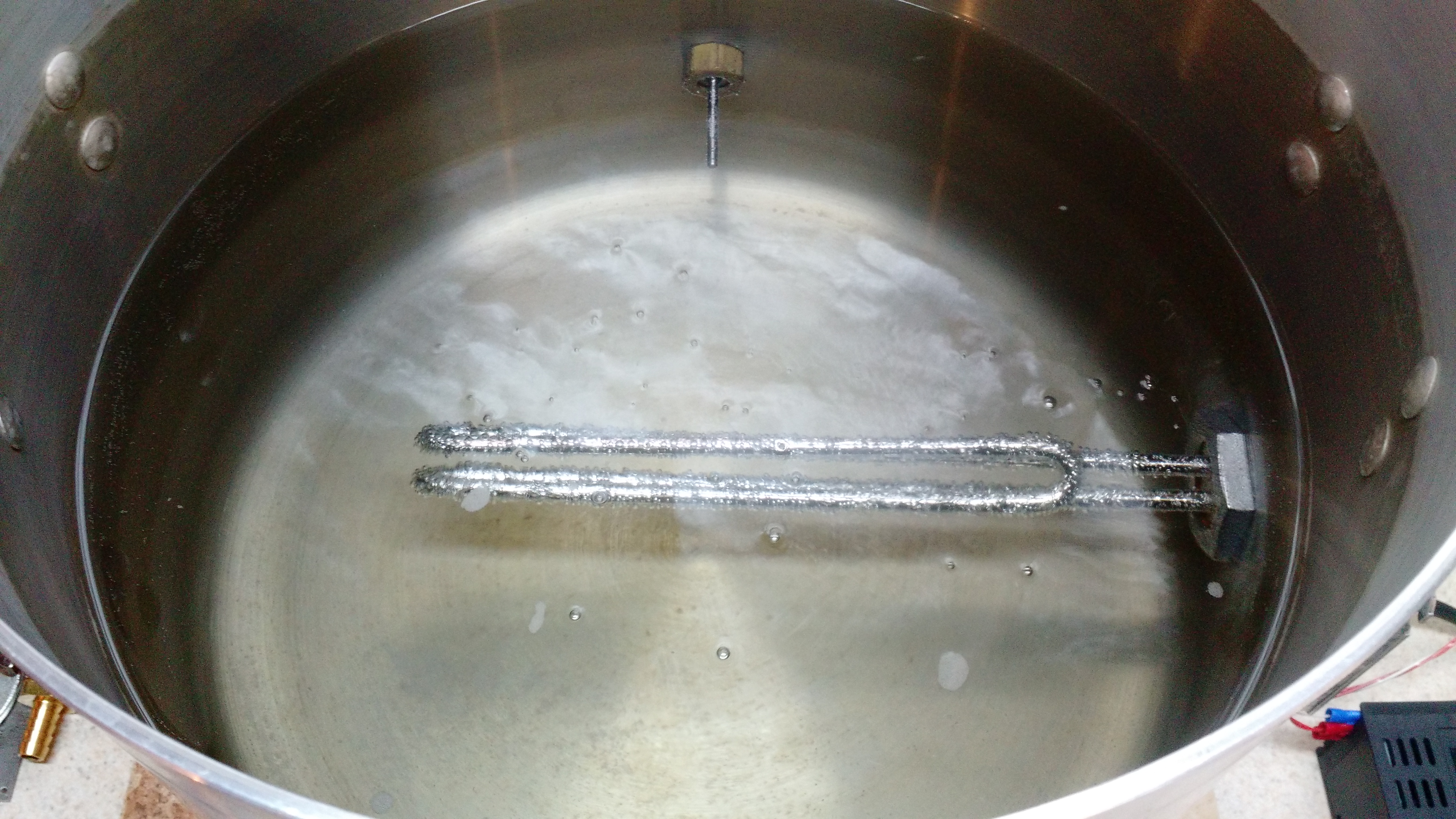
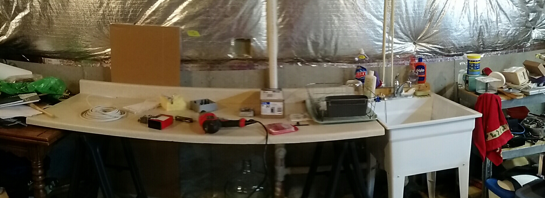
This is the setup. Not perfect, but it works. The switch is for the PID controller (the black box). The SSR is hiding behind the boiler.
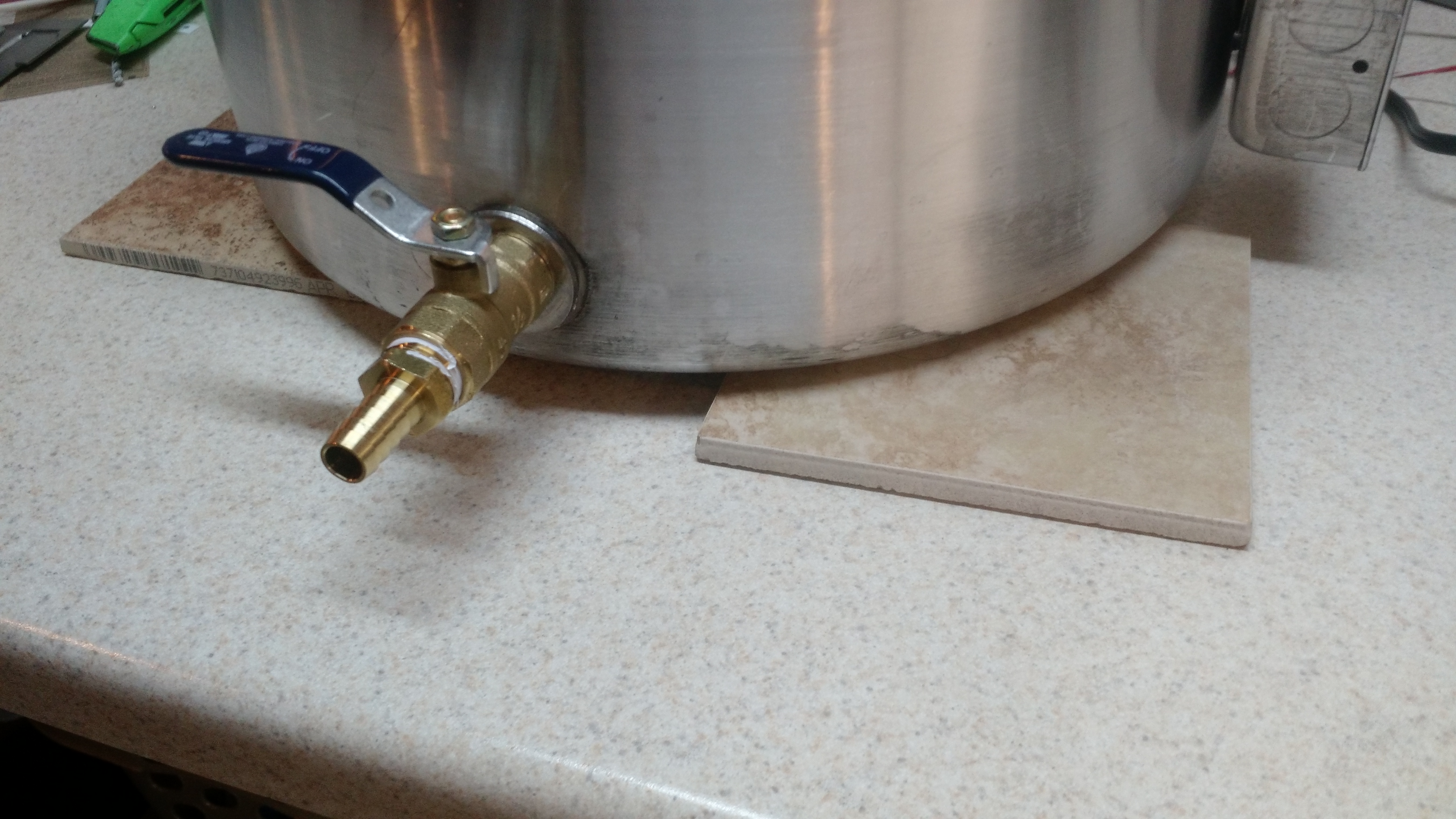
This is my counter protection – 3 6″x6″ ceramic tiles. I don’t think the kettle would damage my Formica countertop, but I don’t want to find out if I’m wrong.

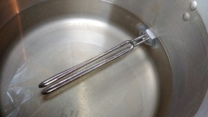
This is the element running and boiling water.
Other Happenings
My cousin was selling a small freezer that would be perfect for us and would replace my current chest freezer with a small upright (and replace a non-energy-star freezer with one that is). Initially I was thinking KEGERATOR!, but after a night’s sleep I thought it might be better to do some fermentation temperature control. That means eventually I will make a schwarzbier, possibly a kolsch, and probably a bock beer early next year.
Cheers!
Brewery Upgrade Phase 2
In the upgrade process, phase 2 is running the 240V line to run the heating elements. This is a hard post to make exciting, because it’s basically all about a wire. And at one time after reading about the death of craft beer on some linkbaitey website (damn you Gose!!! :-D), I thought that I should only make posts that are informative or truly funny, and occasionally respectfully opinionated.
This post is about a boring orange wire.
IMPORTANT NOTE: NOTHING IN THIS IS ADVICE OR A HOW-TO. The voltages involved with an electric brewery are extremely dangerous, and doing things wrong can result in FIRE or DEATH (and it will hurt like Hell the entire time you are dying).
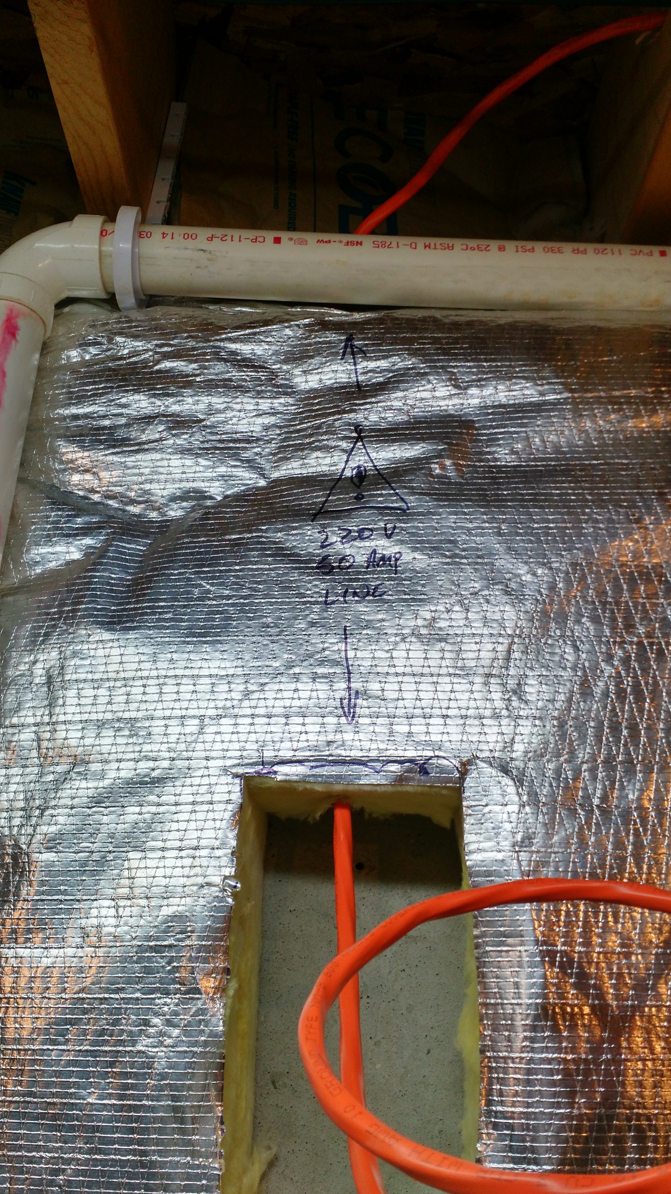
Yay, a boring hole in the insulation.
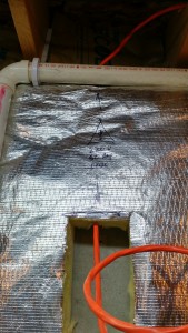
A boring hole with a wire. I couldn’t get conduit behind the drainpipe above, and that drainpipe is NOT getting moved, so I wrote on the insulation that there is a wire there.
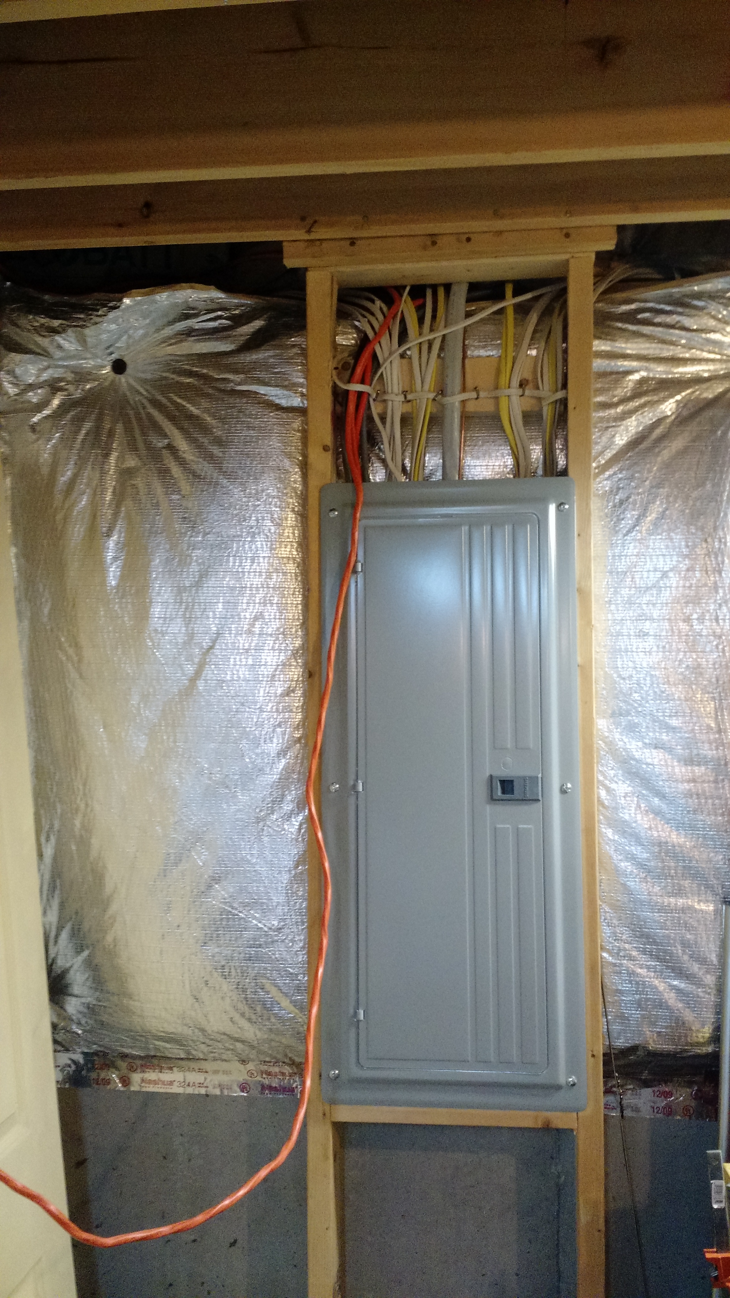
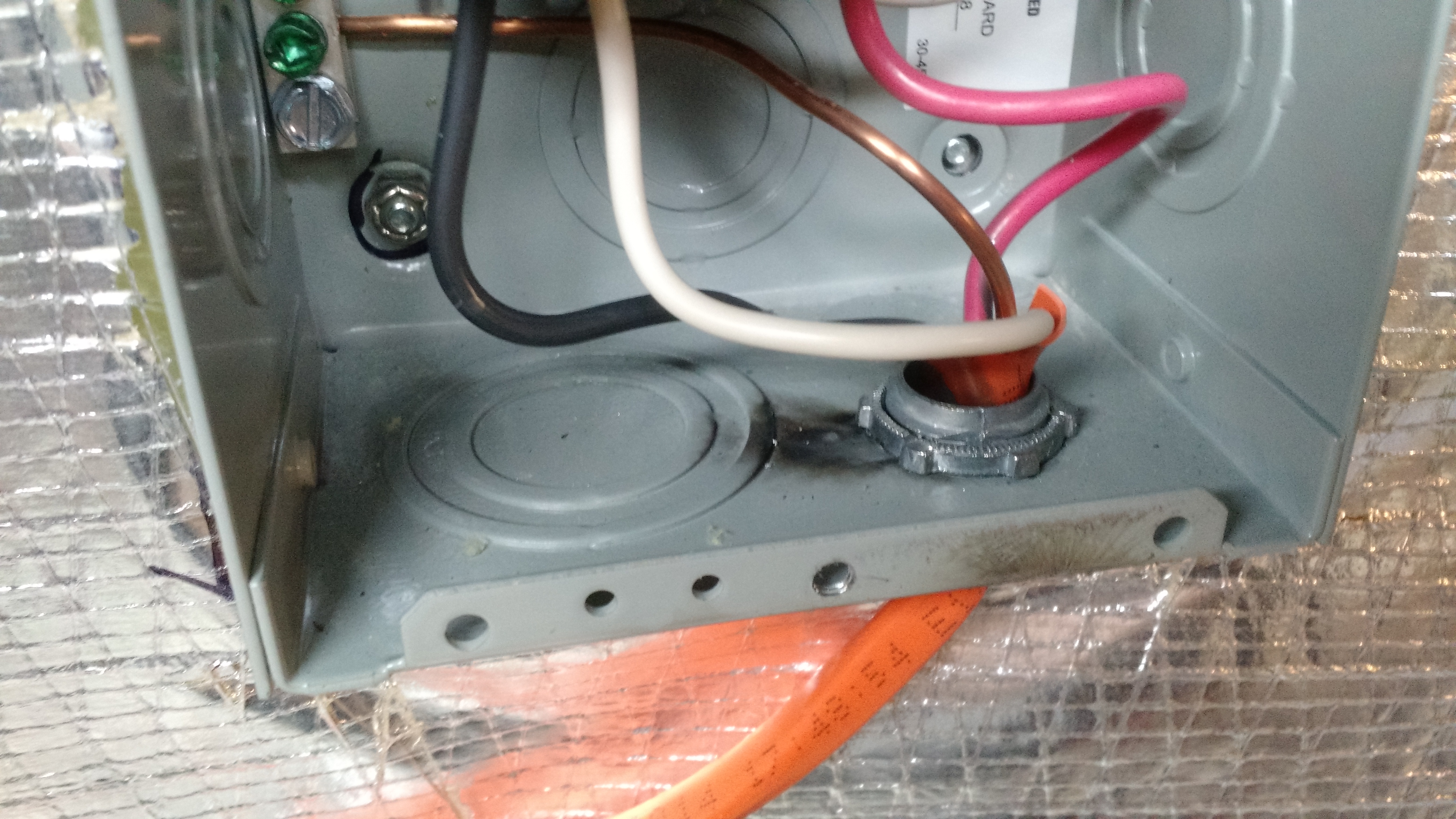
And… a wire. It’s pulled down near the circuit breaker panel in preparation to be run in the panel to a breaker.
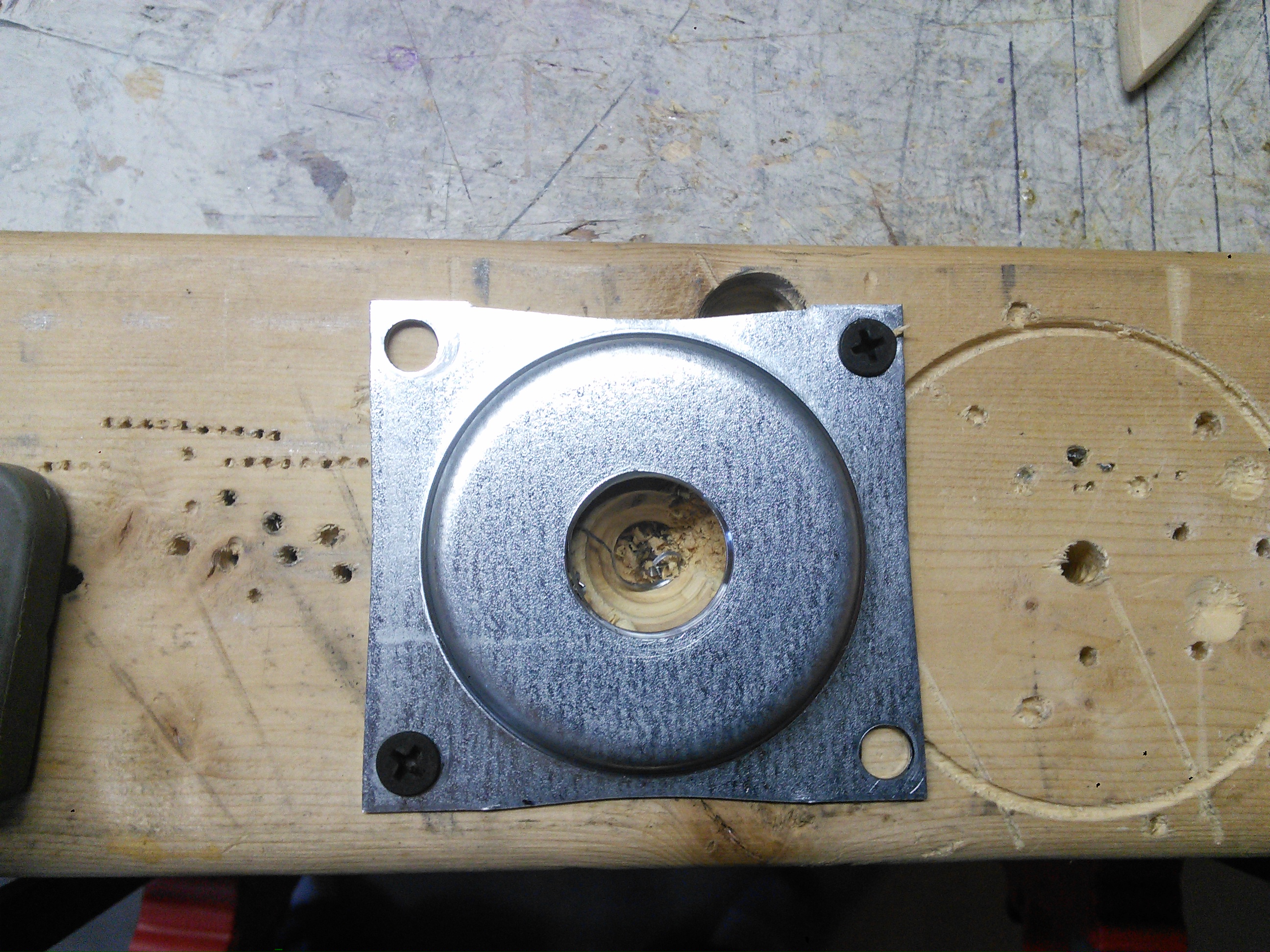
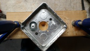
I sometimes have good ideas. Like bolting this piece down to a scrap piece of 2×4 to drill it for a cable connector.
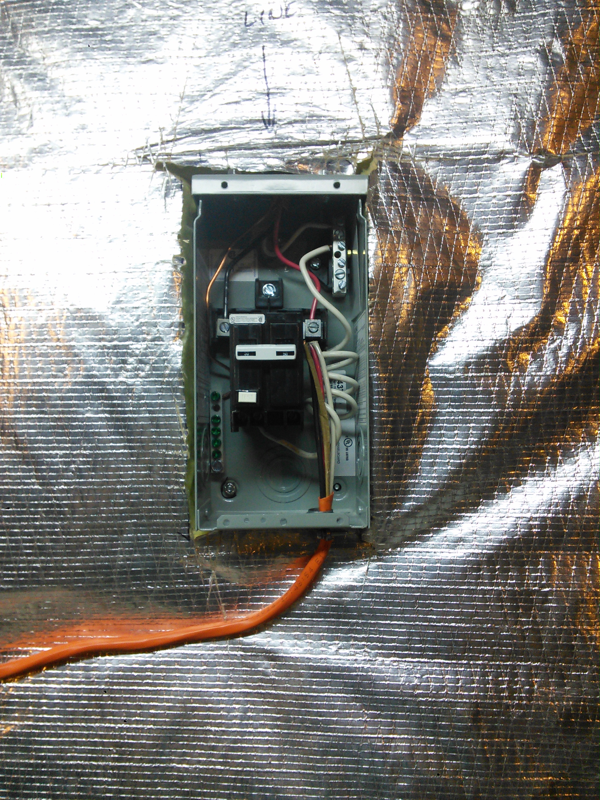
All wired in!
Finish up.
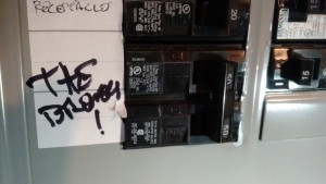
Around this point, I shut off the power and installed the 50-amp breaker.
Drilling the enclosure for the side of the kettle.
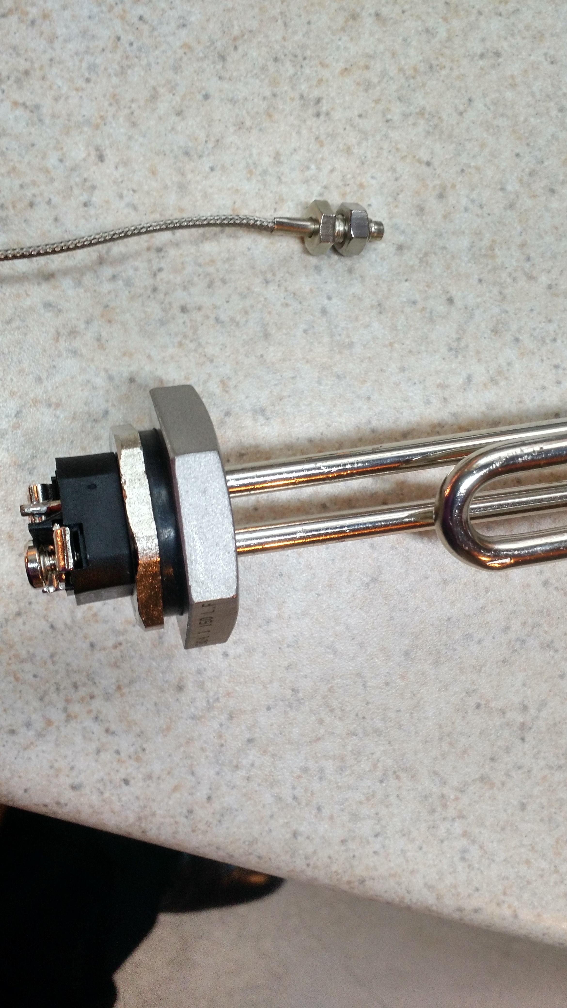
Installed heating element. This took three or four tries to get it installed, and ultimately the wrong washer was the one that came with it and the correct one was a red 1 11/16 o-ring I bought from Amazon.
After this, I decided to turn things on. Unfortunately, I was greeted with a shit ton of sparks.
Not good. Lots of sparks
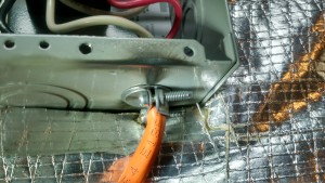
Bottom side of sparks.
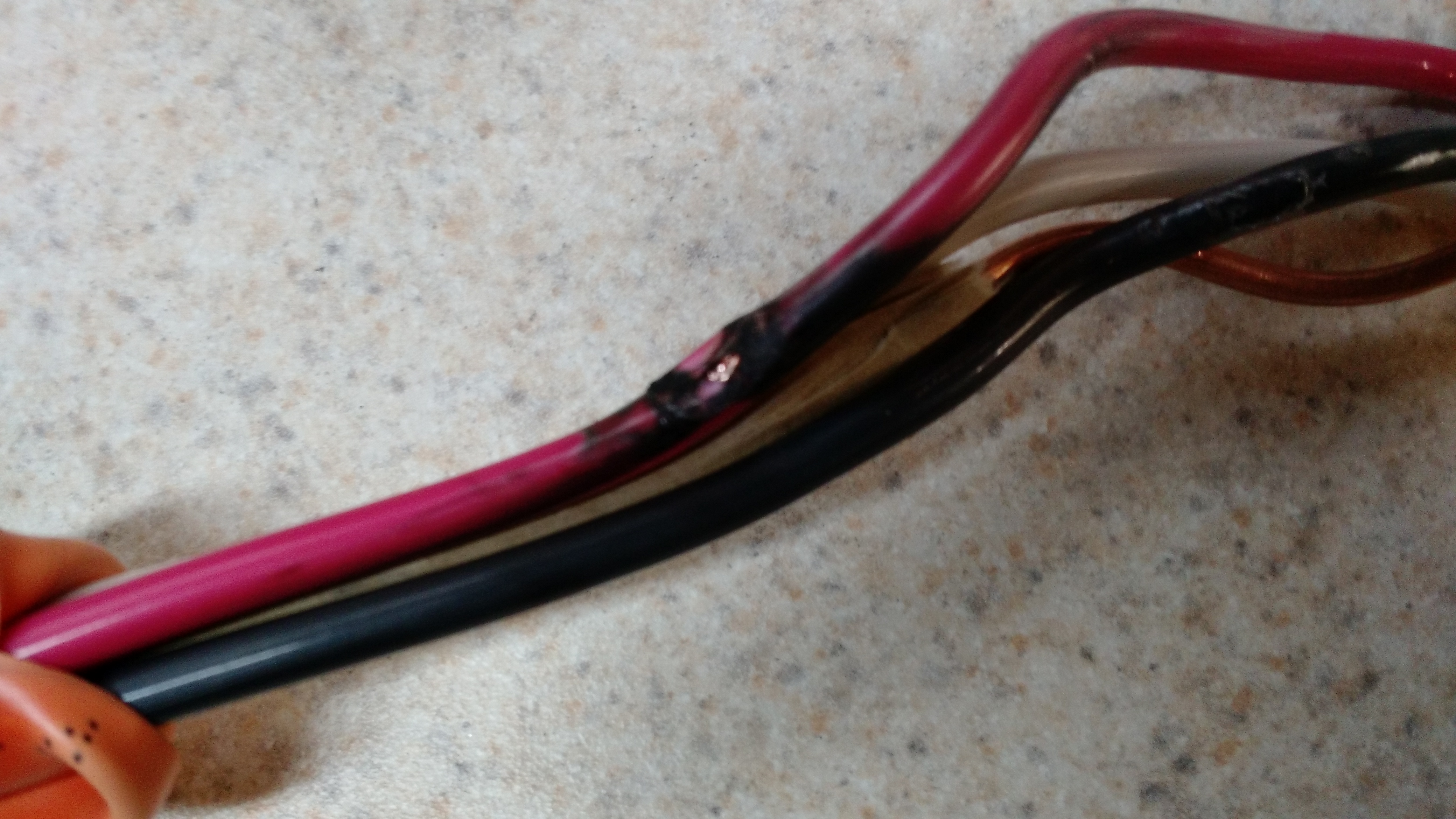
After shutting stuff down and looking into WHY I had a little explosion, I found that I must have pulled the cable too tight and sliced into one of the hot wires. When it connected to ground… BOOM.
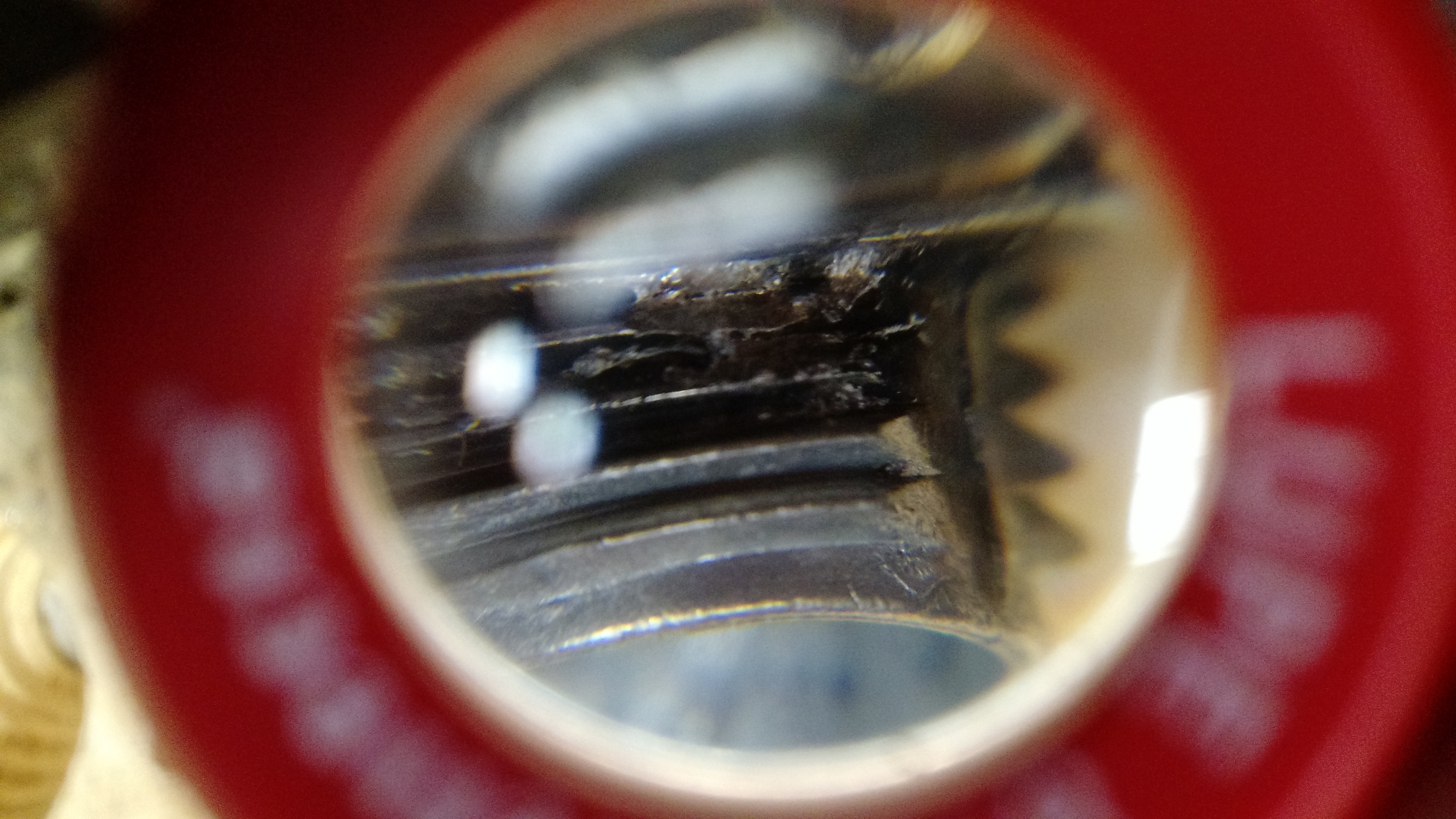
This is the strain relief that the cable was sliced through. This did come right out, fortunately, as the heat from the arcing was enough to do some damage to the threads. Had it been longer, it could have welded in place.
While a large part of this post was quite boring (seriously, it’s a wire!), I’m really excited about it. Not the wire (even I think the wire’s pretty darn boring), what will happen when I get the rest of the stuff wired in and I can brew beer in the basement.
Cheers!
Playing with a PID
In the process of building the electric kettle, I bought a PID (proportional-integral-derivative) controller to control the kettle temperature. Since this came from Amazon and had Chinglish directions, I figured I should get it out of the box and test it.
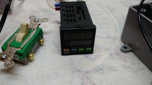
The Controller
The controller is a little 1.75″ x 1.75″ (45mm x 45mm) square. The screen has two displays, one for the temperature, one for the set point. There are also four buttons, SET, <<AT, up, and down.
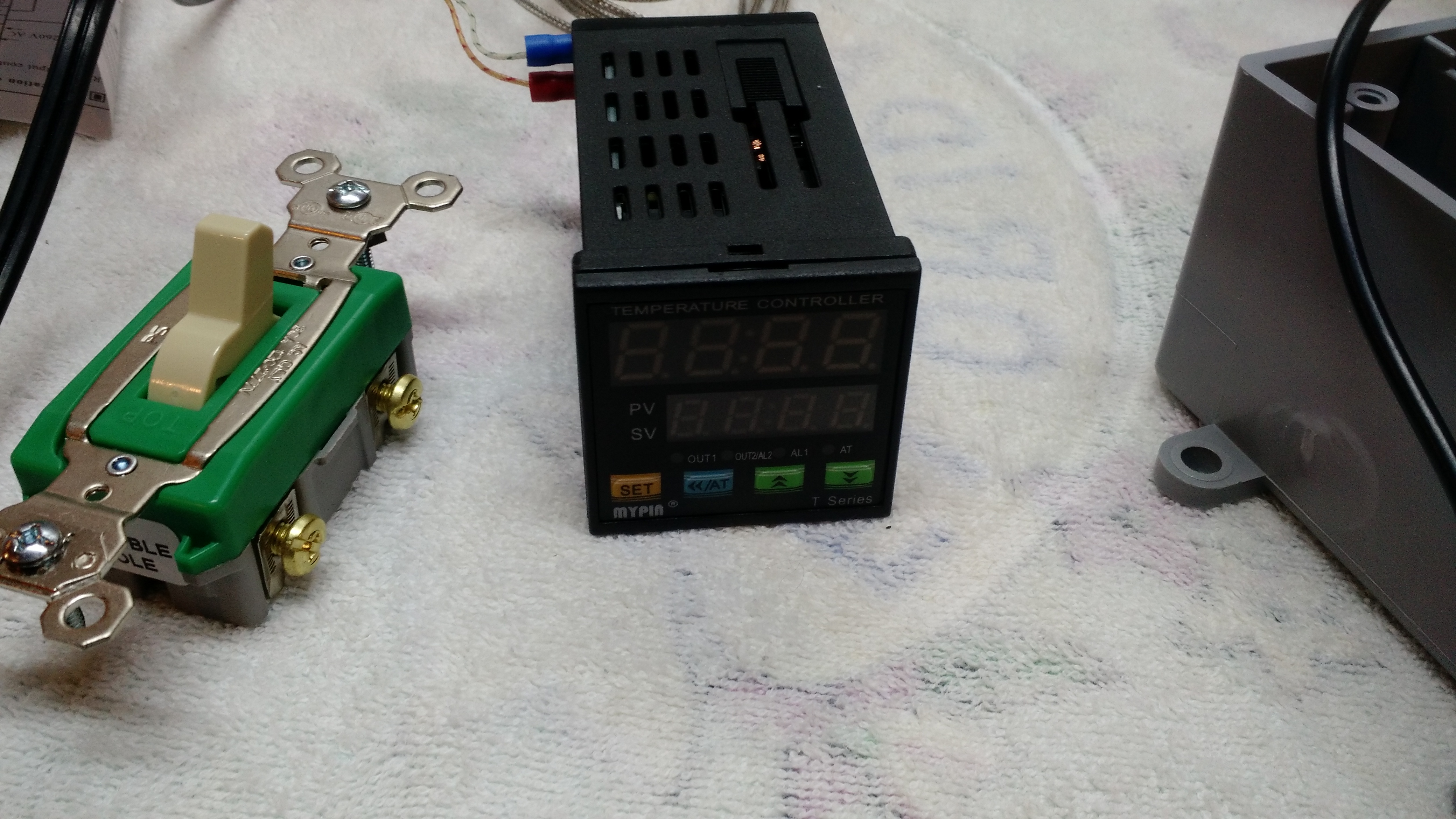
Test Setup
I threw together a setup that has a switch (in this case, a double-pole switch built for 220V 45A), a plug, and the PID.
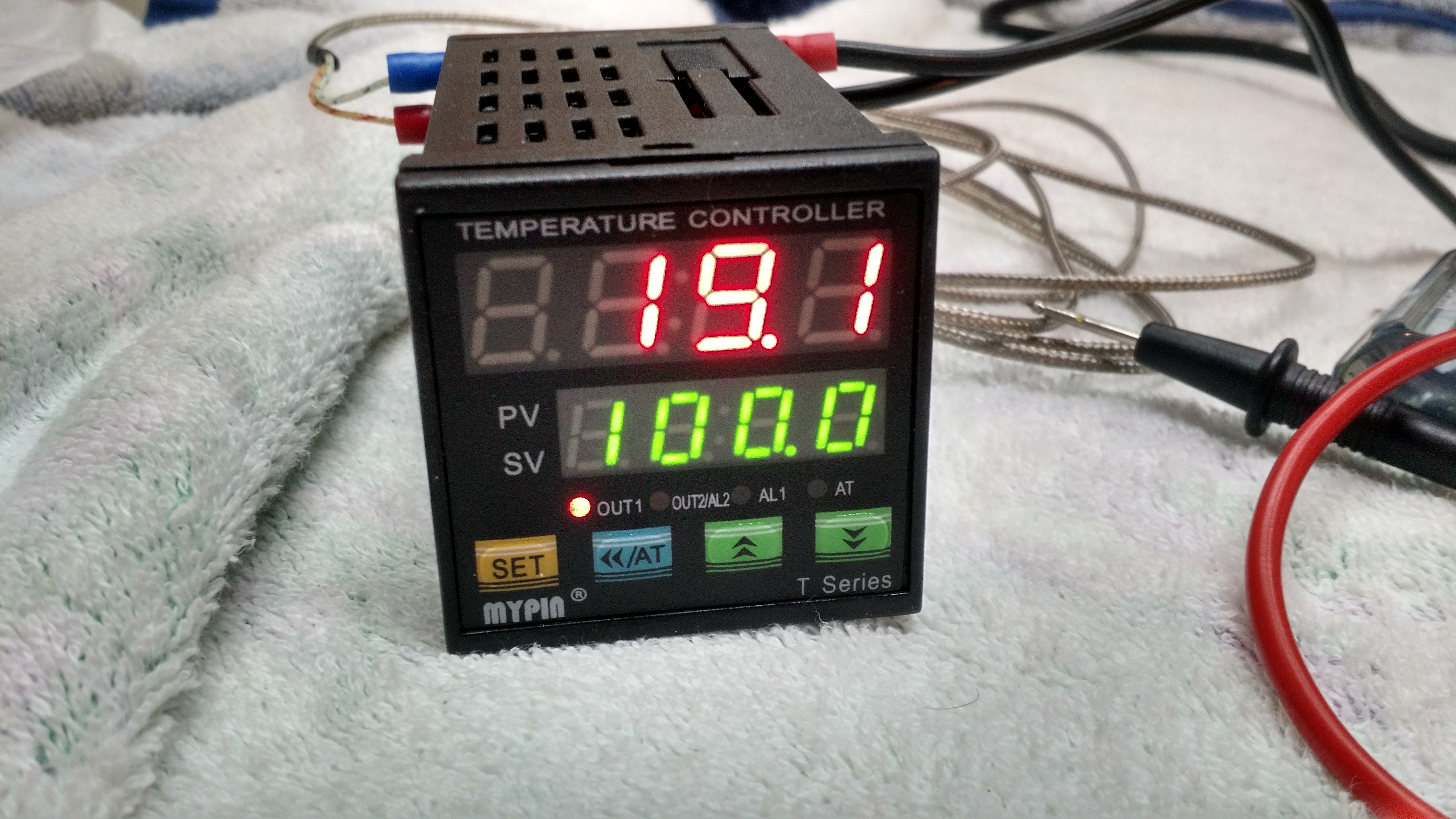
Running in Centigrade
Initially, the PID is setup in Centigrade. You can change it by holding down ‘set’ for a few seconds and then pressing it until you see a C F in the upper screen and using <<AT and up or down to change it from C to F.
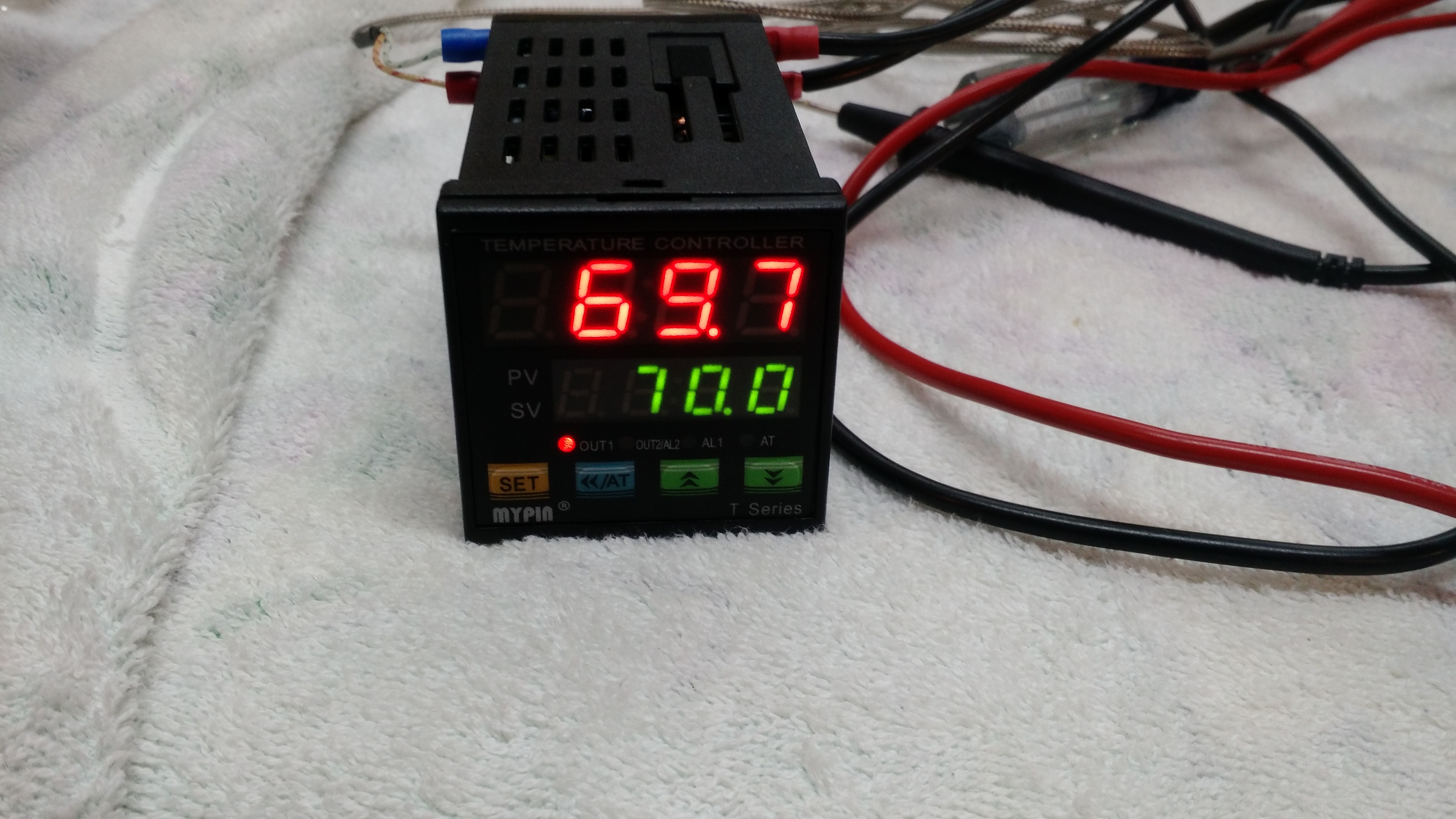
Switched to Fahrenheit
The output is 24 VDC. There is also an alarm that is basically a switch (normally opened, closed during an alarm condition). The set includes some slip brackets (that’s probably not the proper name) to mount it in a box.
The issue I ran into with this is that the thermocouple is a less-common thread size – I don’t have the correct size nut and my tap set doesn’t have the correct size, either. I did find the right size at the hardware store (a 6mm nut).
I also had to find the right locknut for the heating element. Apparently, this is standardized to a 1″ nut, and they run less than $4 at Grainger.
Almost ready for drilling
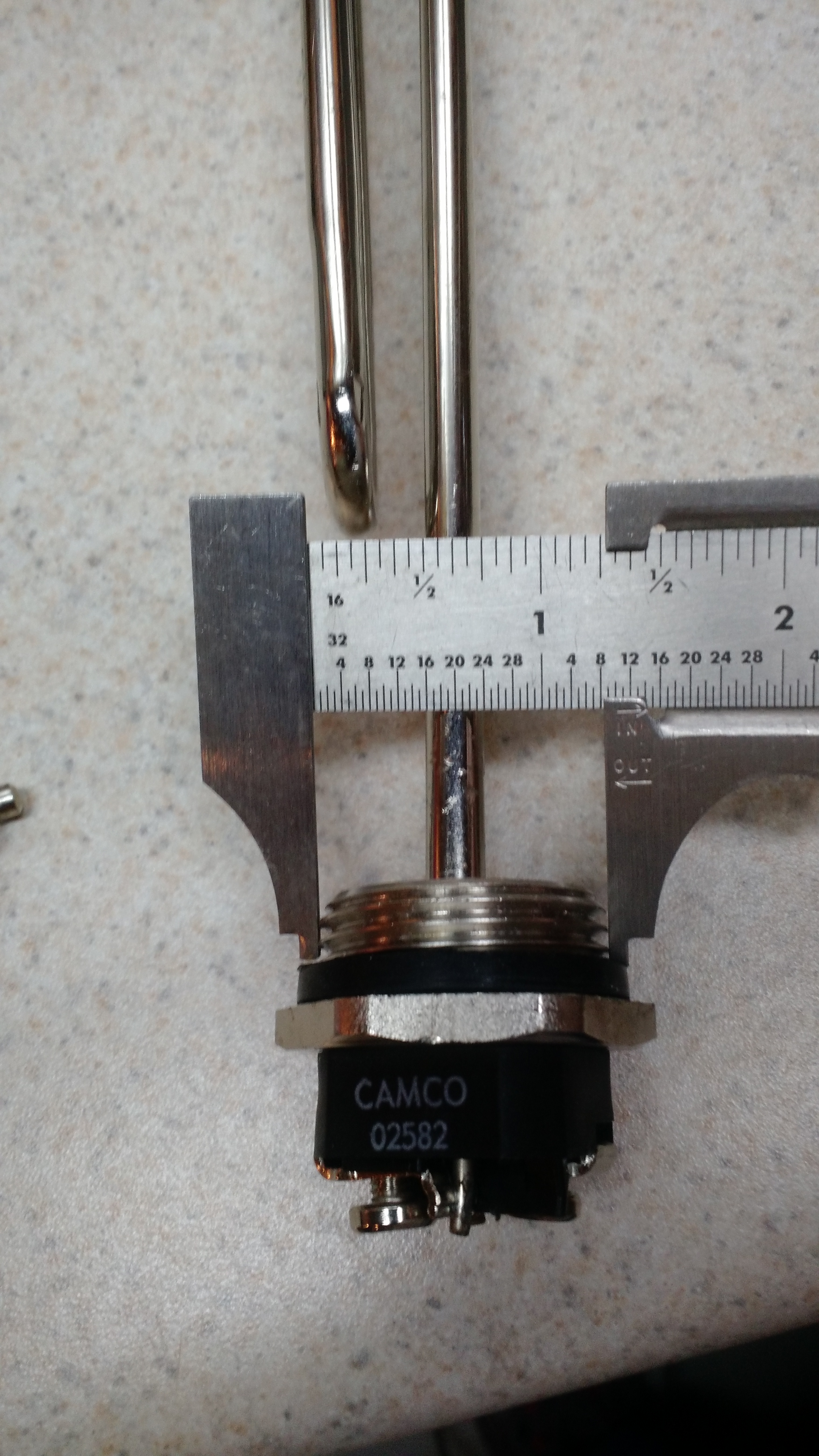
1 1/4″ outside the threads
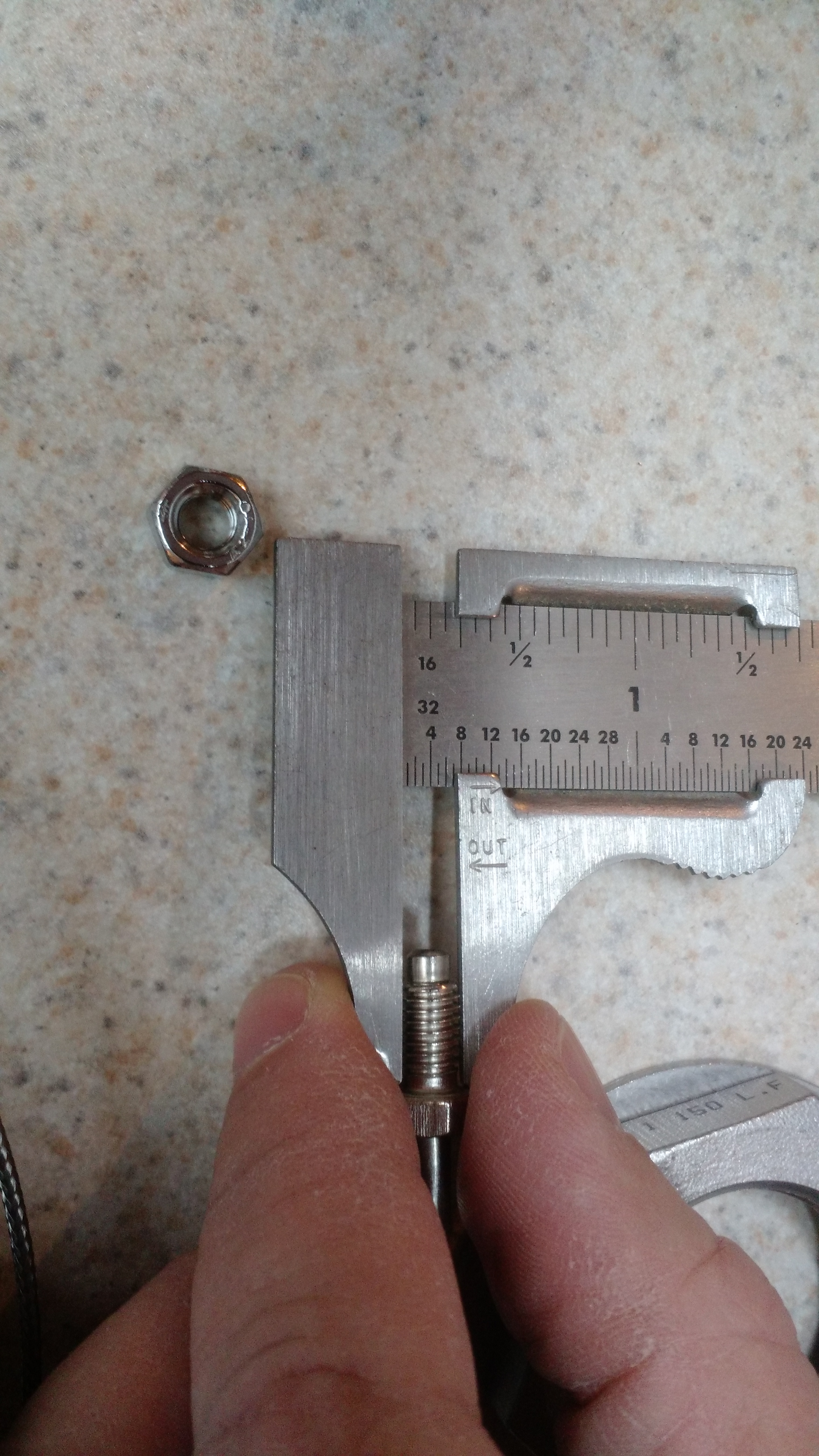
1/4 inch outside the threads
So the next post should include something about getting this running in sort of a basic semi-usable and somewhat unsafe configuration. I’m sure my 50 amp spa panel will be part of things, as well as the switch I used above, and the PID controller of course. However, the PID controller won’t be controlling anything until I get the solid state relay. That’s probably stuck in the harbor outside of Long Beach; fortunately it shipped a few weeks before the Chinese New Year, and you really only need a few days (if that) for it to leave China and not be affected by the holiday. So the delay is all on Long Beach.
In the meantime, I ordered a pair of SSRs to be shipped from Georgia. Which will probably arrive next Monday.
Cheers!
Brewery Upgrade Phase 1
I did the first phase of upgrades. This wasn’t a whole lot of work, but after spending quite some time at the hardware store, it was enough to cap off the rest of a day.
Semi-before
So the first part was an outlet somewhere near the brewing area. I’ve never actually needed an outlet for brewing, but the counter sometimes serves other purposes (my food dehydrator, for example), so having some outlet space is useful. Plus, if I want to plug in a radio, my phone, or something like that, I don’t want to run an extension cord across the basement. Safety first and all that!
DISCLAIMER: I am not an electrician. What I’m documenting here is a result of research mixed with a little bit of theoretical knowledge and some experience. This is not a guide or how-to on how to do this.
So extending the outlet isn’t difficult. Black to brass, silver to silver, and bare to bare. Running it is a pain, but hooking up wires is easy. Testing is easy.
Test
Every
Outlet
Sometimes twice (note the GFCI light is on, I pressed the test button and wanted to ensure that the other outlet was actually protected)
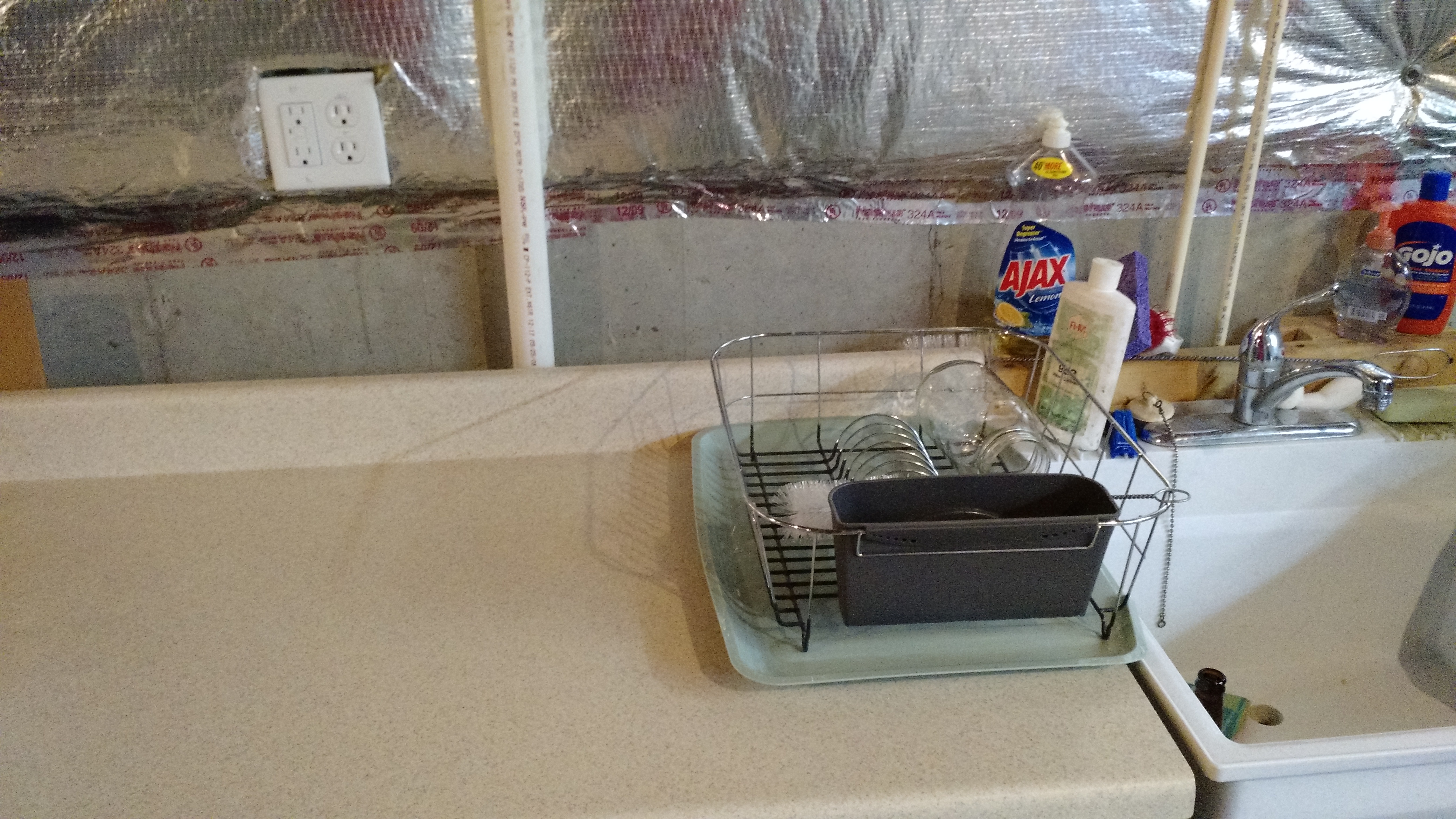
Finished outlet
That was the first part of the improvements. The second part was another outlet, but this one was for a light. I tied it into a light socket nearby.
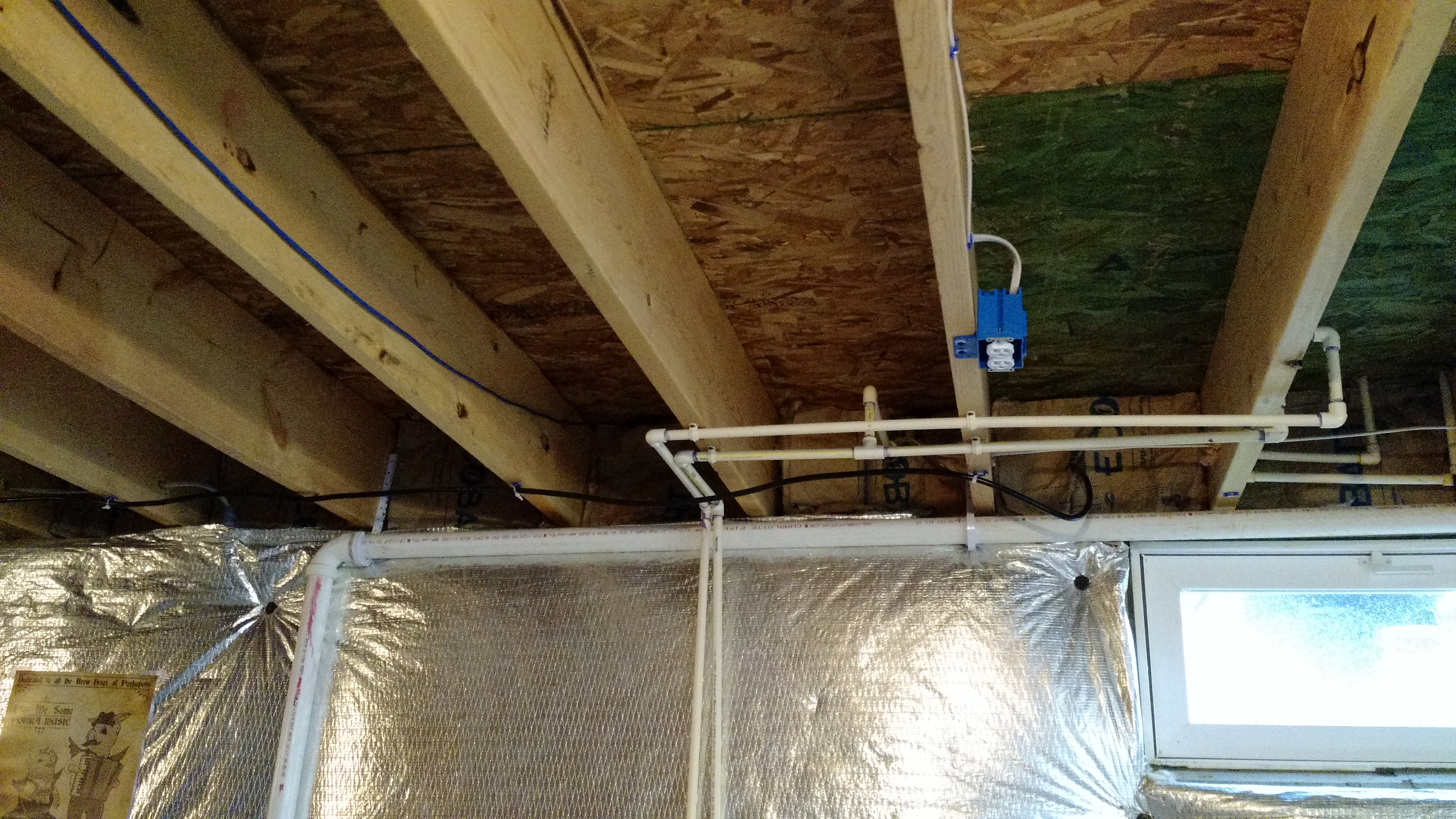
The outlet.
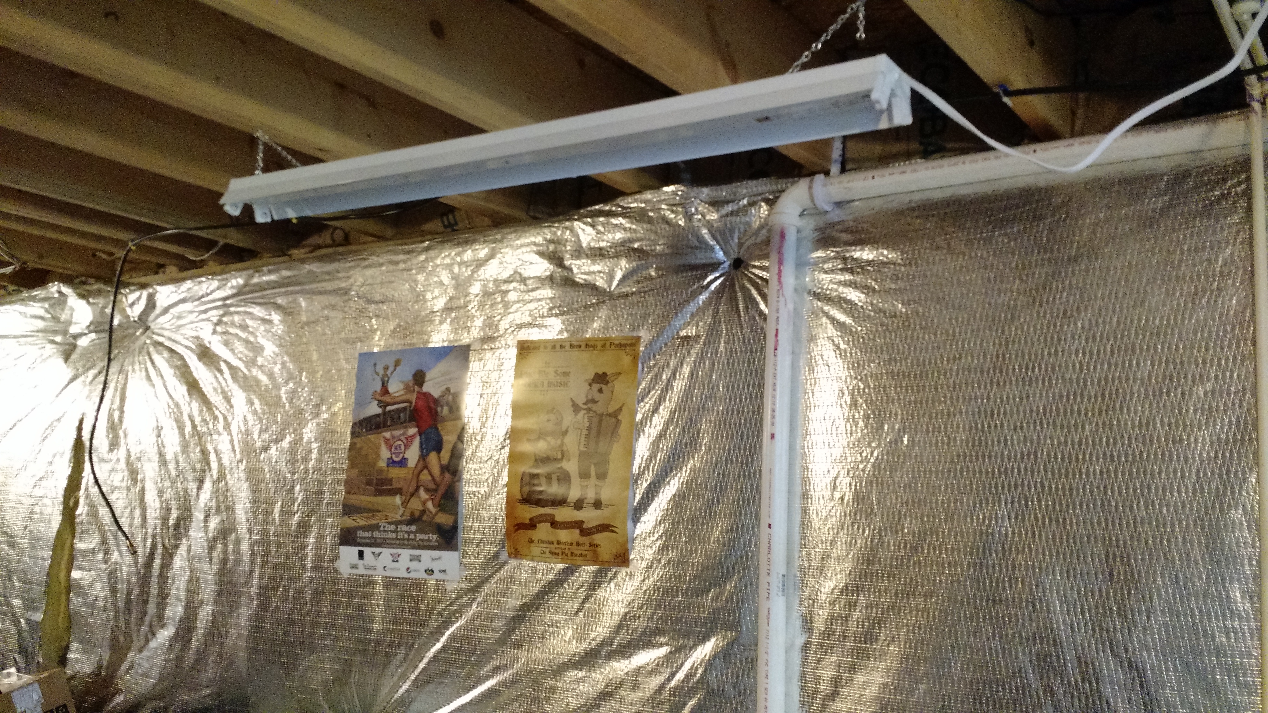
The finished light, sans bulbs (they didn’t come with the kit). This will operate with the switch to turn on all the basement lights.
So that’s phase 1.
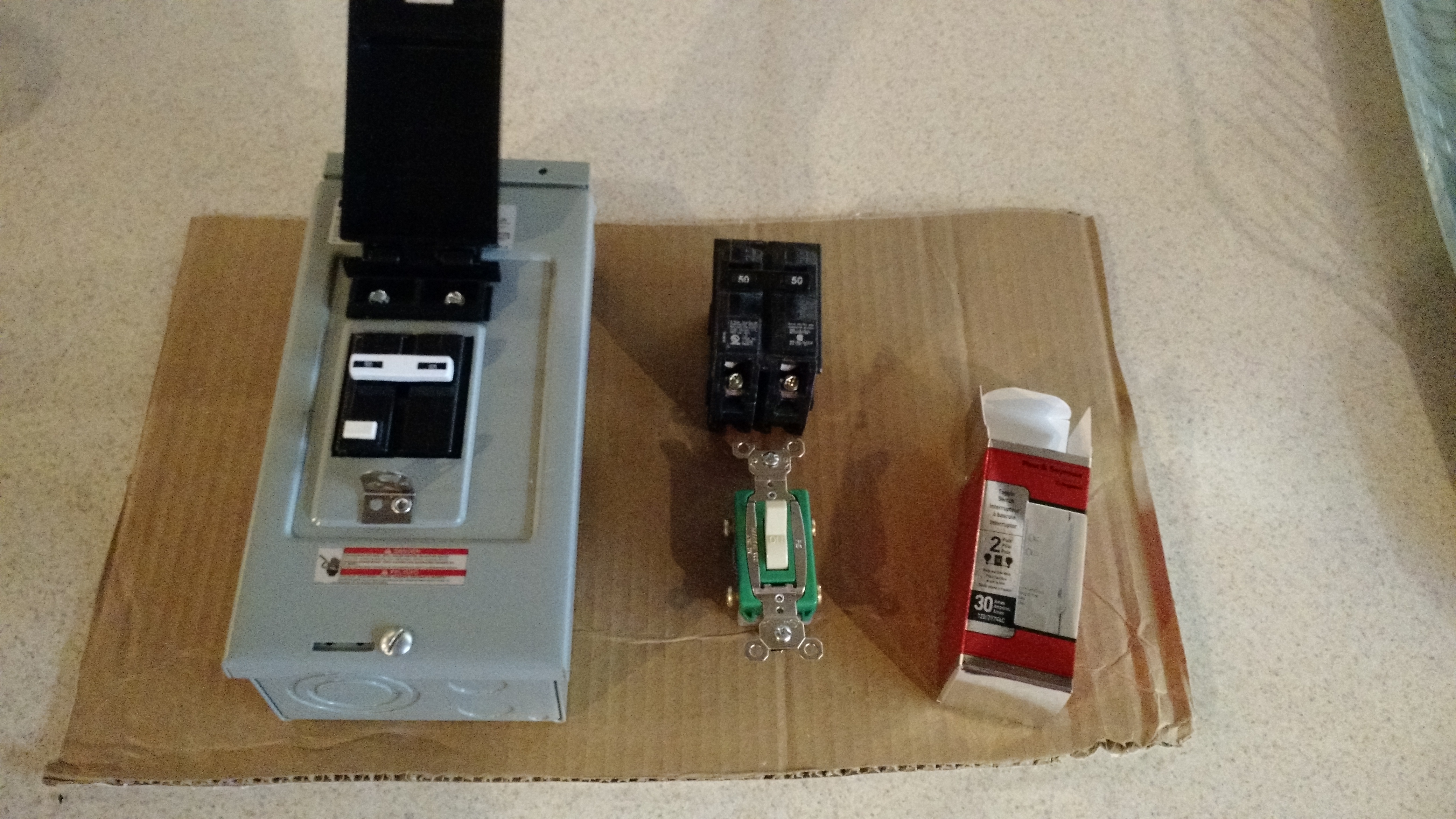
Components of Phase 2
Stay tuned for phase 2
Cheers!
New Brewing Setup Plan
After the last beast of a brew day, I want to fix my setup to make the next brew (soon, hopefully) easier. I don’t need all the fancy-pants pumps and stuff, but I do need a good way to heat water quickly and safely. Convenience is pretty important to me as well, so I’m not going to brew in my garage (no sink and poor electrical and poor lighting).
So I drew (literally) my plan.
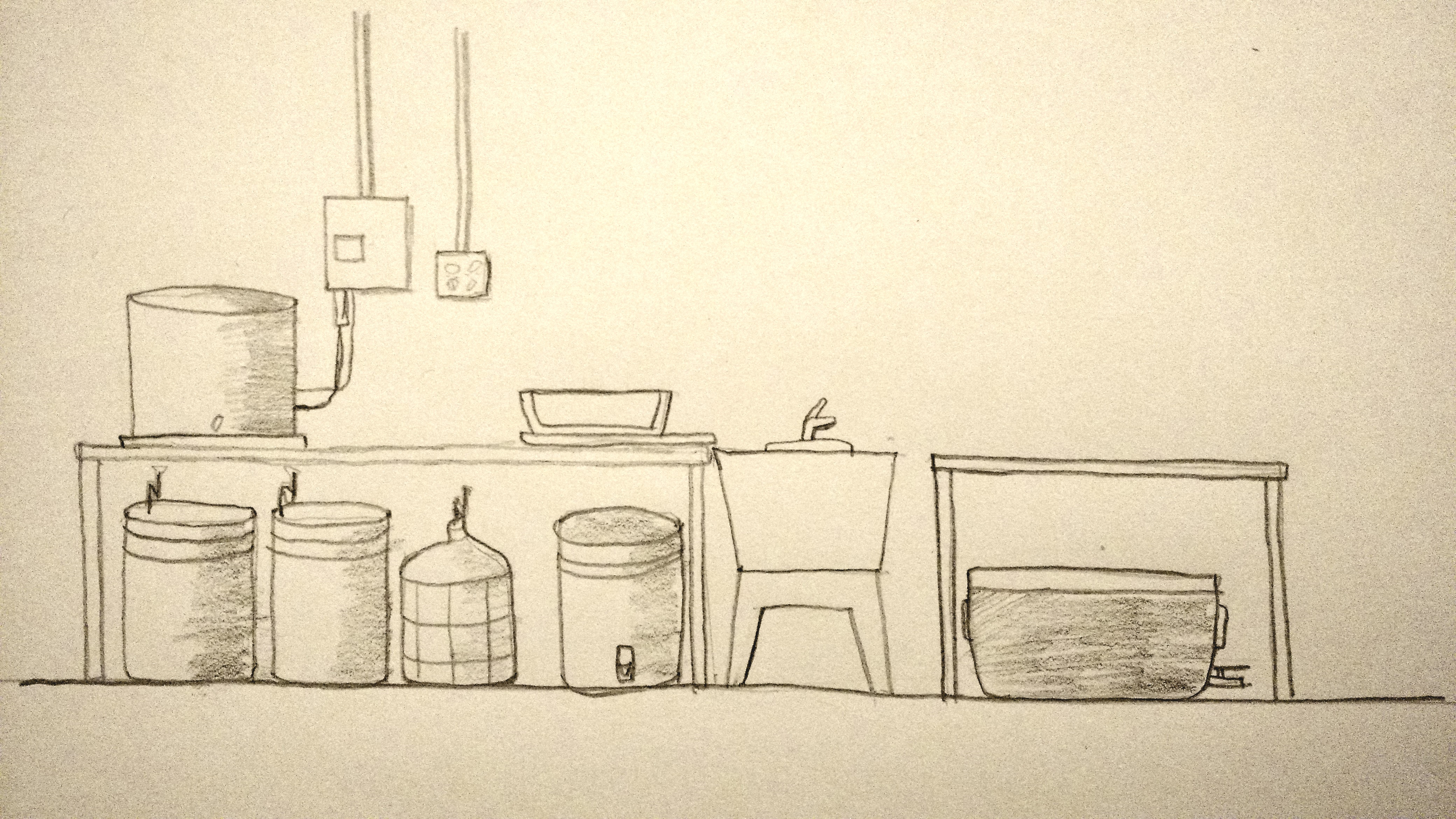
New Setup!
This is a plan in four phases, and since I’m looking for content, I’m going to have a post for each phase.
Phase 1: 120v Upgrades This is minor upgrades to the electric at my brewing area including an outlet at the brewing station and a better light.
Phase 2: 240v Wiring This is the major part of the wiring. I’m not afraid of electricity at all (I’ve been shocked a few times), but I do take care (which is probably why those shocks weren’t enough to kill me).
Phase 3: Control Box Since I don’t have hundreds or thousands of dollars sitting around, I’m making my control box myself.
Phase 4: Finish Up and Testing I’m not doing all this stuff for my health! There’s a few things that will have to be added in, like a pump. Realistically, I’m going to need to another kettle, too, but that will be a while.
Cheers!
Mash Sparging Sprinkler
Edit: I’ve decided that this is a bad idea. There is a TON of heat loss through this. Don’t do it unless you have a way to maintain temperature in the mash tun.
I have a brew in the fermenters, and my first all-grain batch is going to be … interesting.
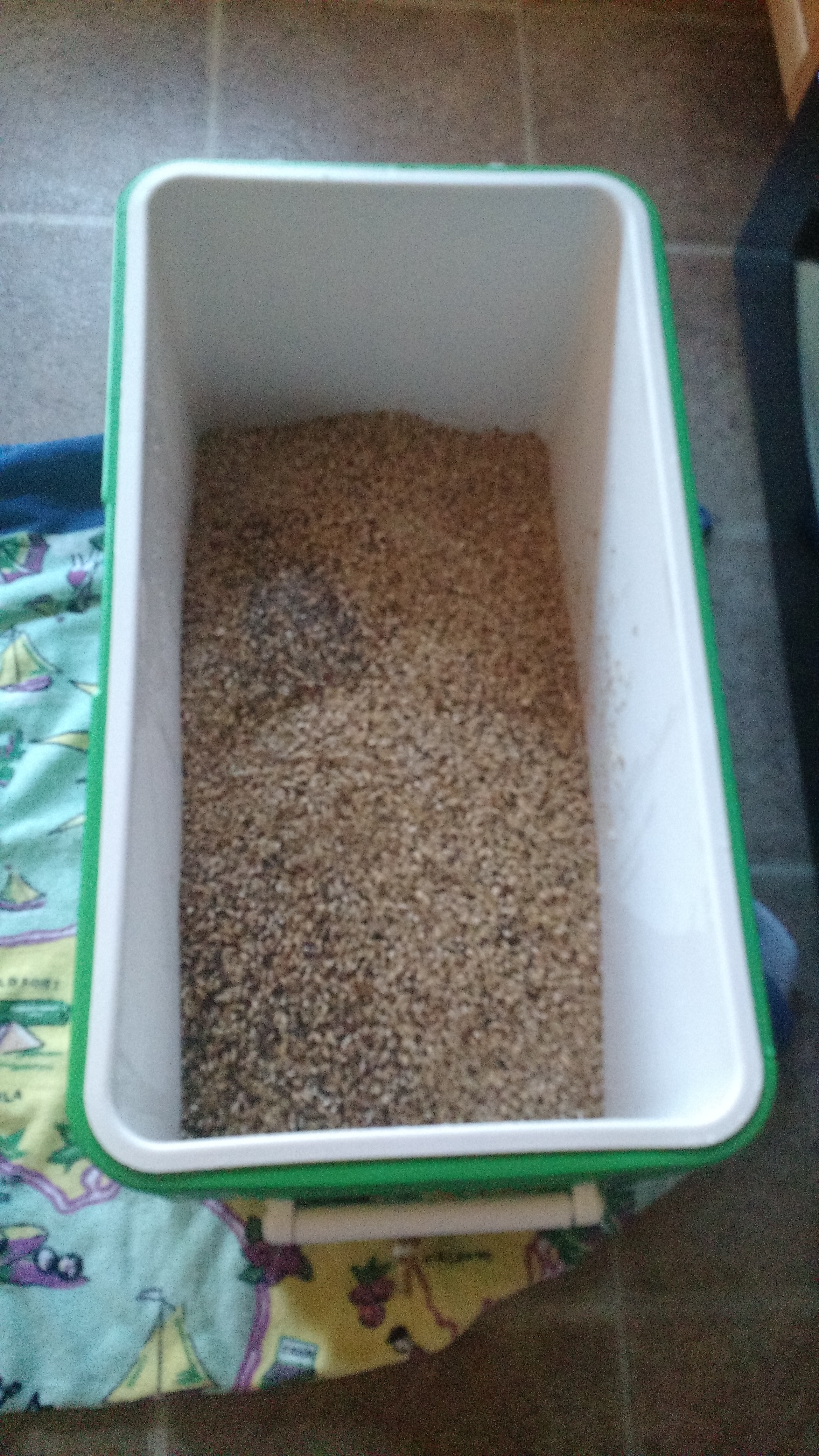
My first mash
One of the reasons why it will be interesting is because of the lack of a good way to evenly sprinkle water into the mash. So I fixed that problem.
In place and ready
Ready for me to add the hose barb connector.
There’s a ton of holes off the bottom of the holes (I say off the bottom because I drilled at about a 30-45 degree angle from the bottom, this would hopefully equalize pressure. I won’t be pushing a lot of water through this, as it will be coming from the hot liquor tun through 5/16″ hose with only gravity as pressure.
Next brew day is coming up. I can’t wait.
/A
Building a Mash Tun
A few weeks ago (and I think I posted something quick about it here), I bought a 12 gallon cooler to be used as a mash tun. Over the past week and weekend, I started getting it together.
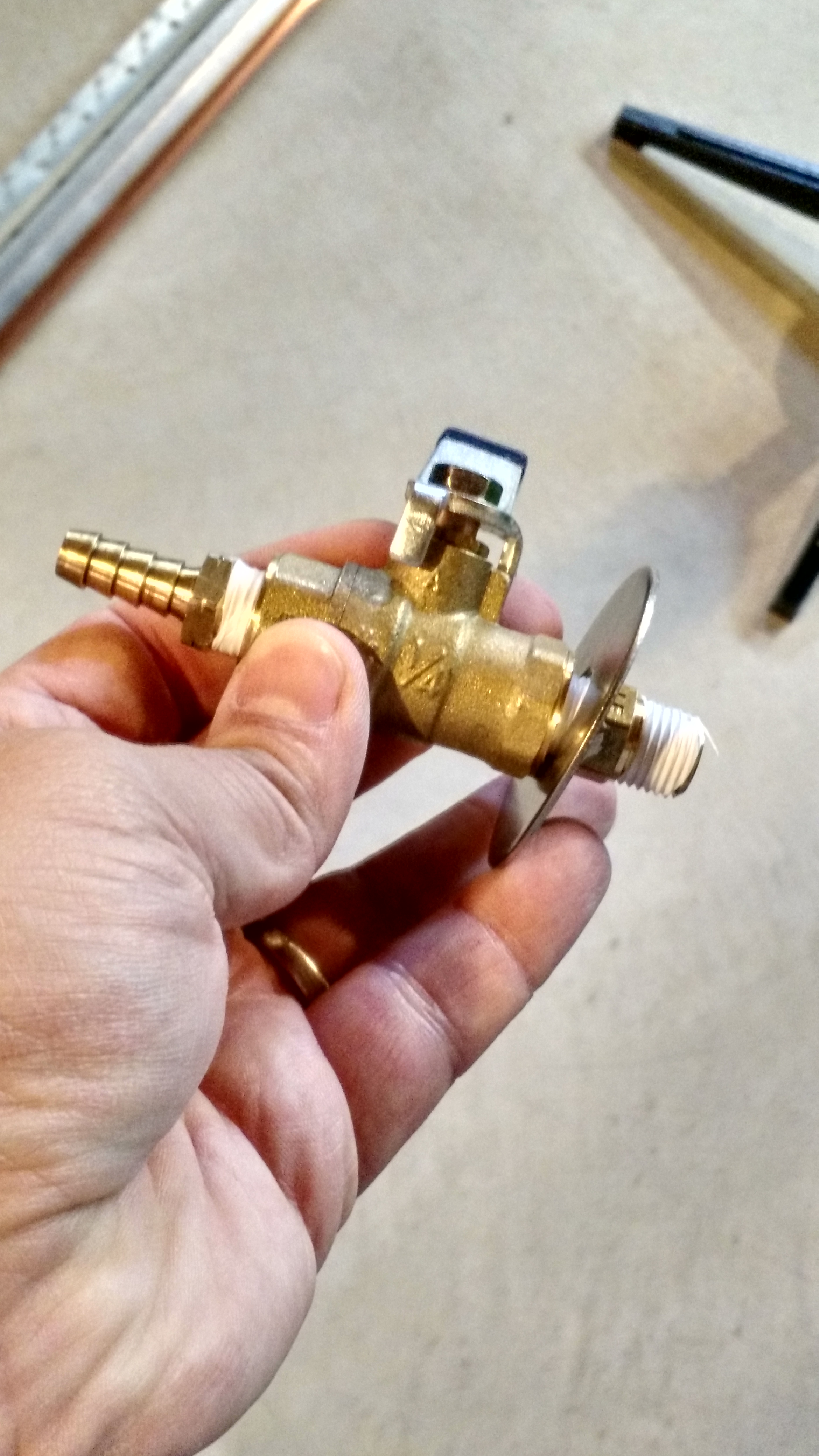
Ball valve with washer and … fitting.
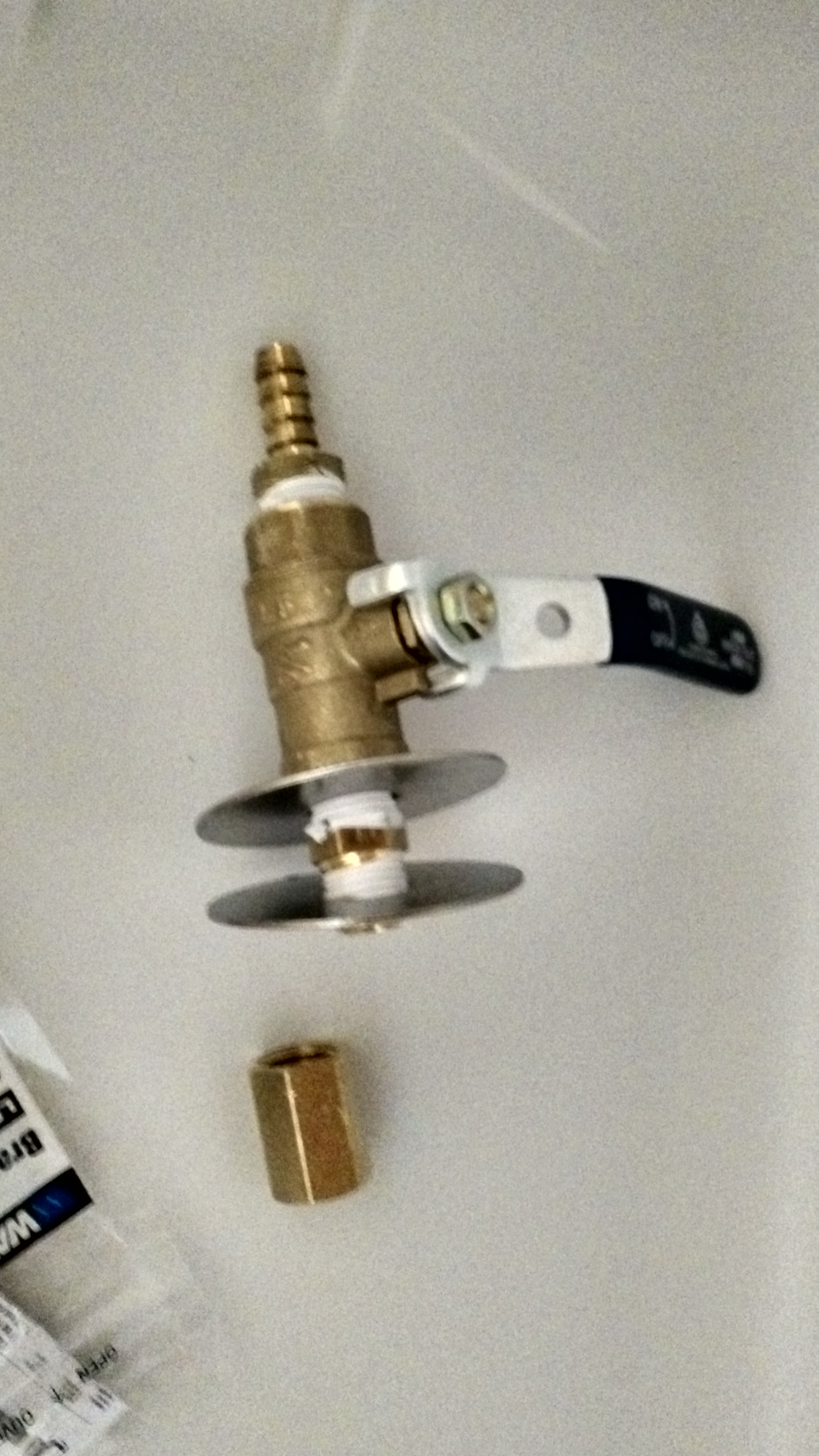
This is sort of the way things went together. I did add some exterior caulk between the internal washer and the cooler to provide a water-tight fit (and I tried several times to not use the caulk, but there seemed to be no way to do that without ending up with a leak).
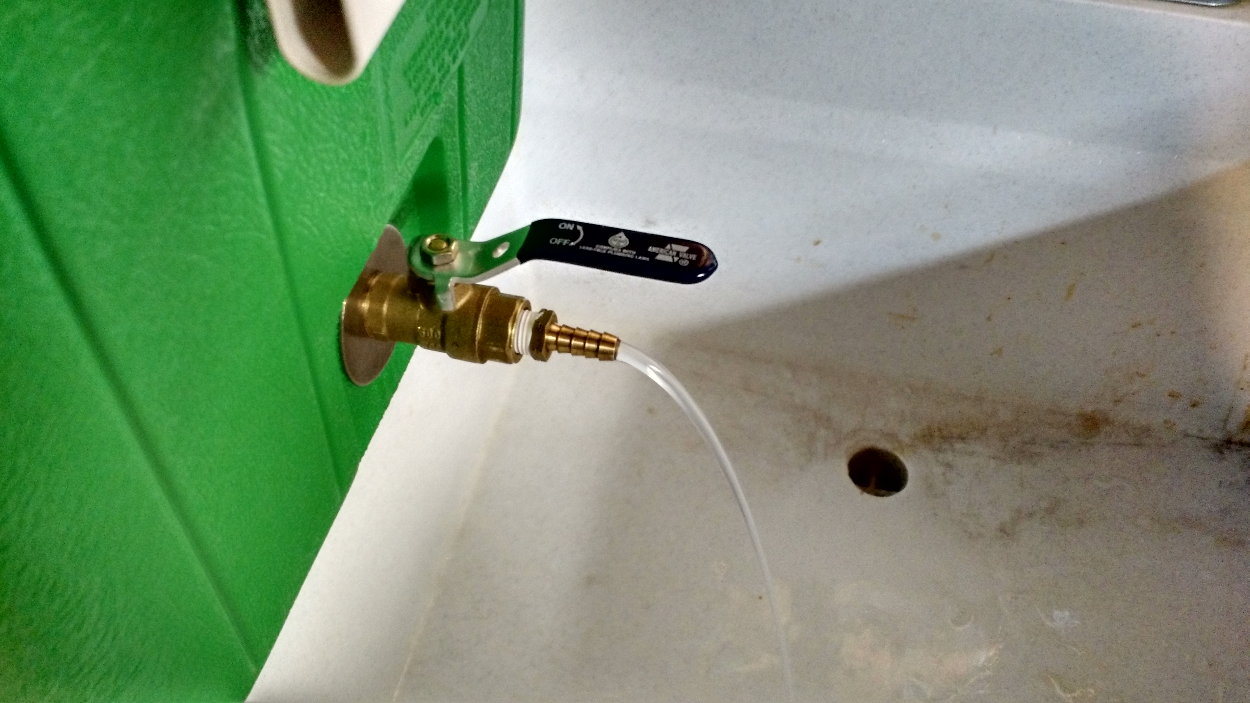
All fit and no leaks (after the fourth or fifth try).
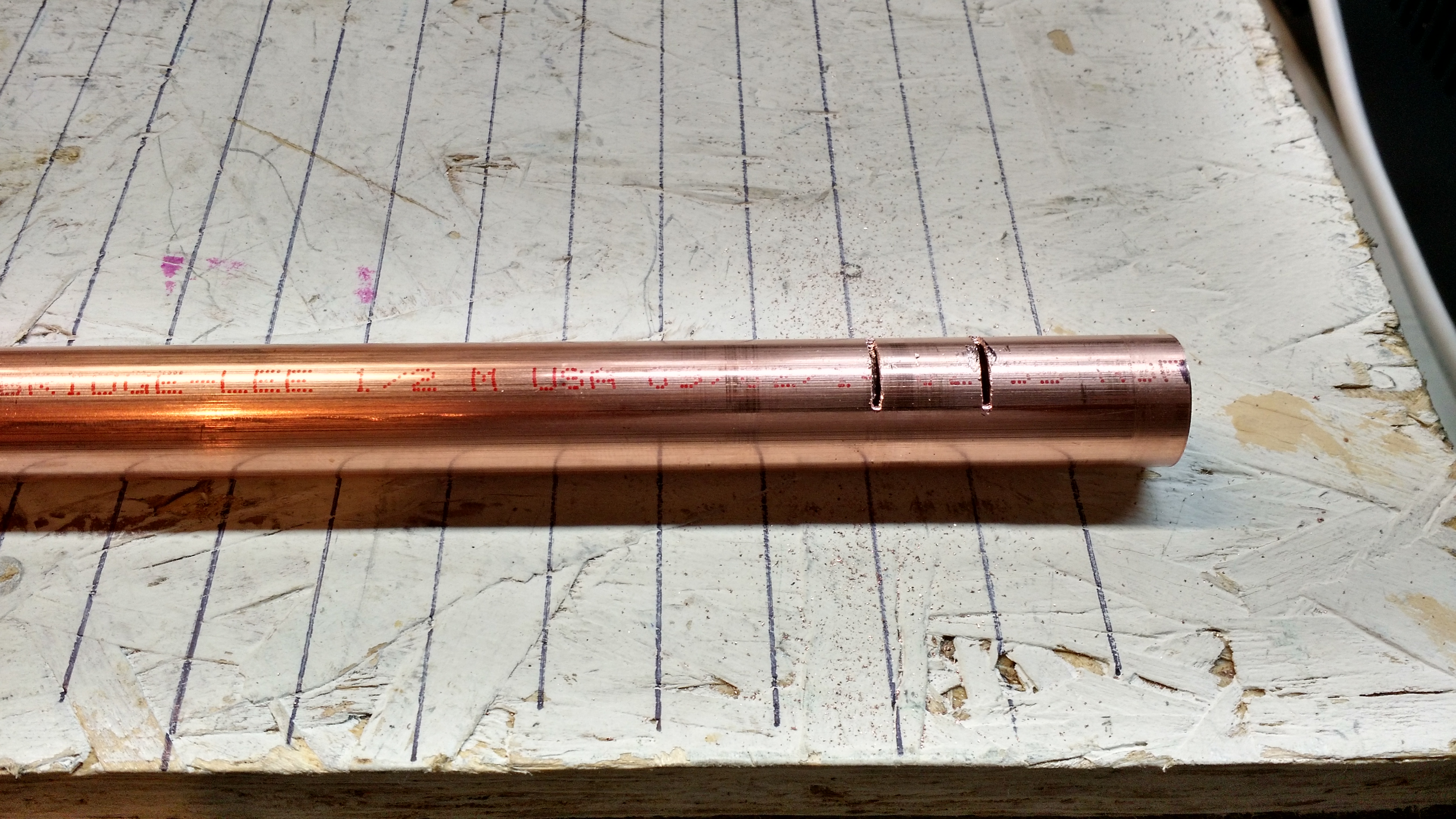
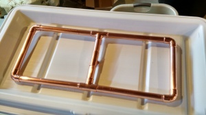
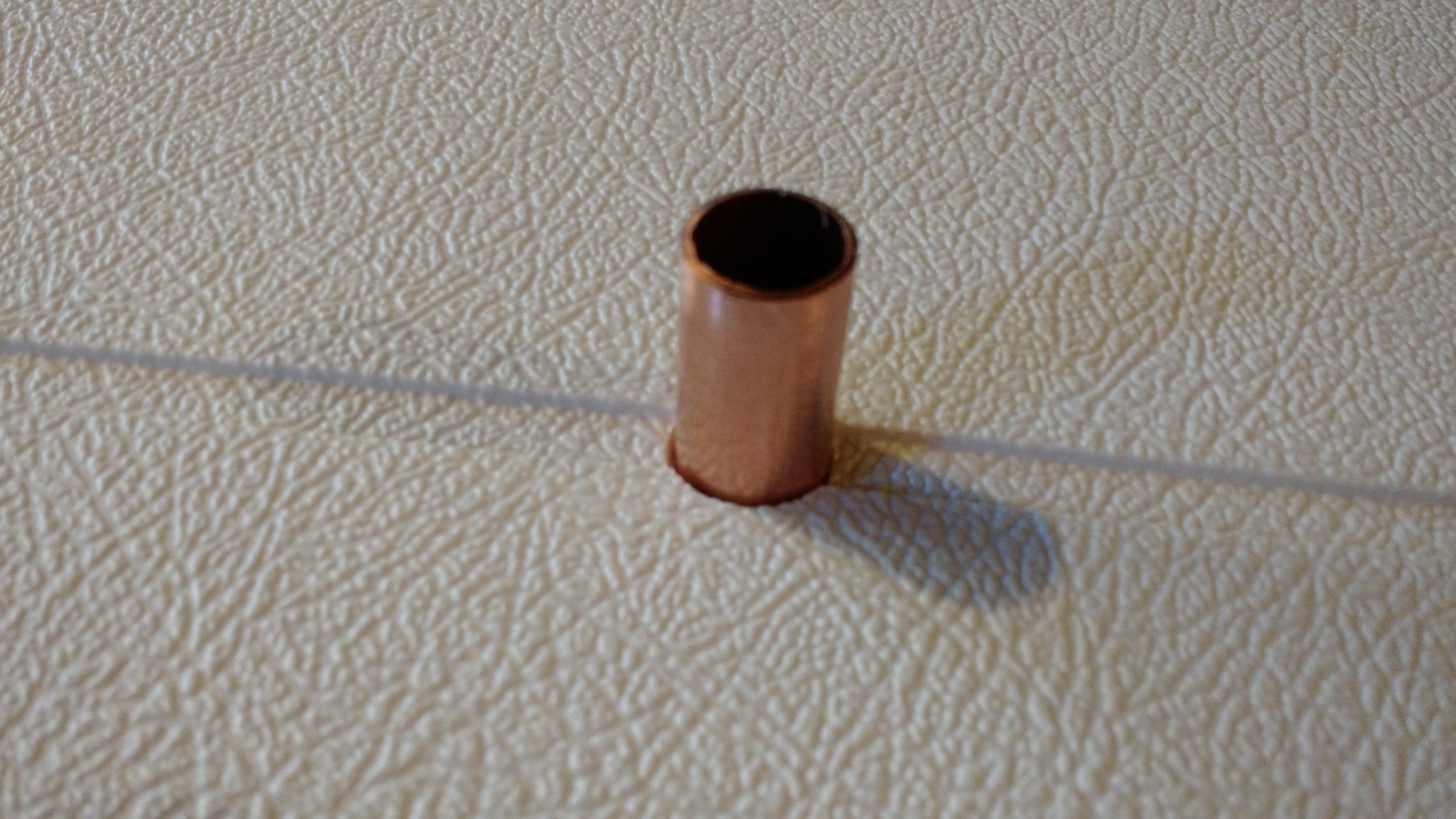
Starting on the copper for the drain lines. This is clamped down (gently!) on one end and I drew lines on my workbench at 1/2″ intervals to speed the process of sawing the slots.
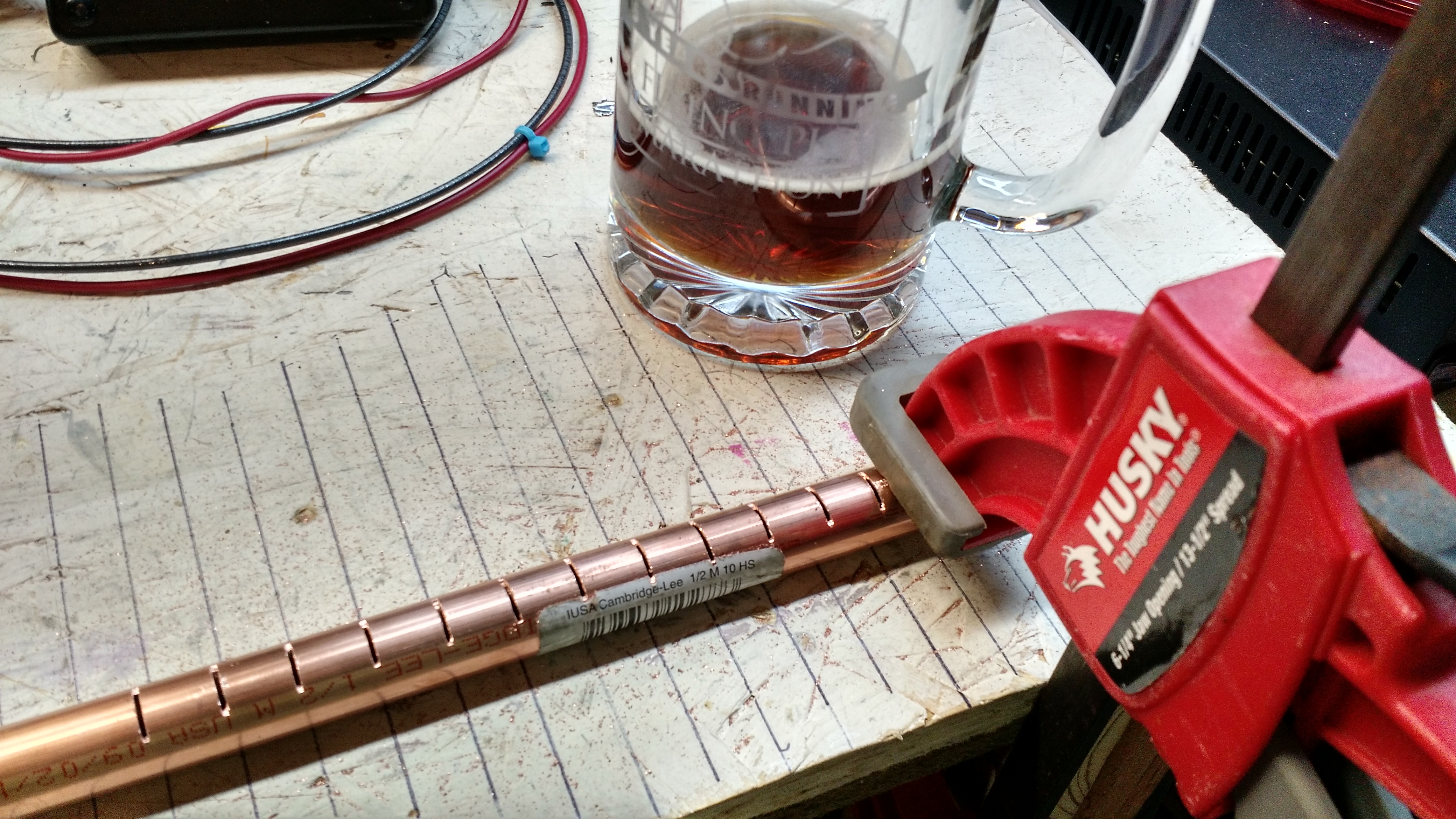
Sawing the lines.

Interior of the lines before cleaning. I found that a 1/2″ drill bit fit through the 1/2″ copper, so I ran it through a few times to remove the burrs.
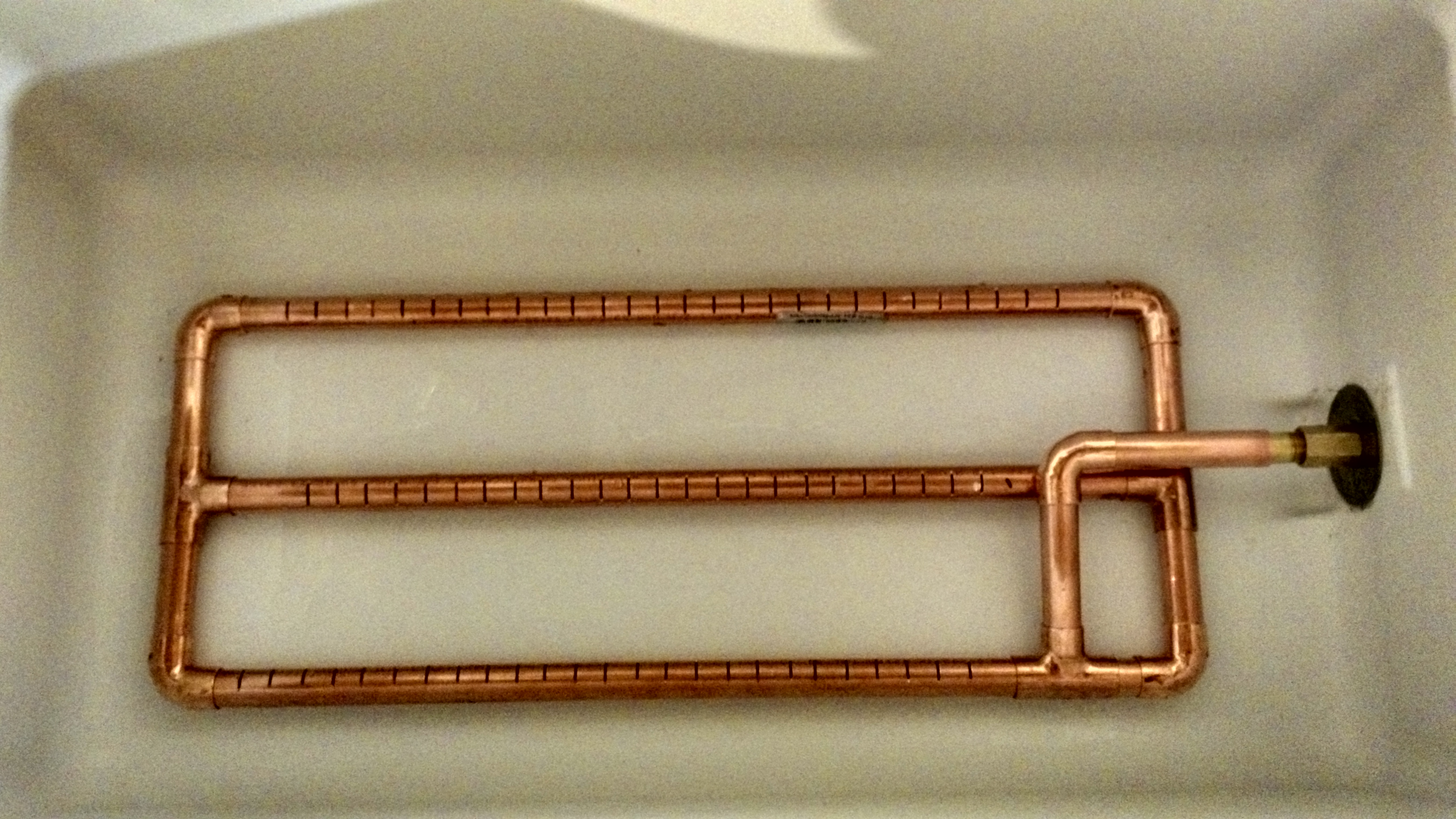
The lines all in place prior to washing with vinegar and then soap and water.
Beer Update
The IPA is probably ready to be bottled, but I spent all my time doing yard work, building my mash tun, and fixing a Christmas tree stand that nearly sent a tree tumbling last year (She Who Must Be Obeyed was NOT happy about that!).
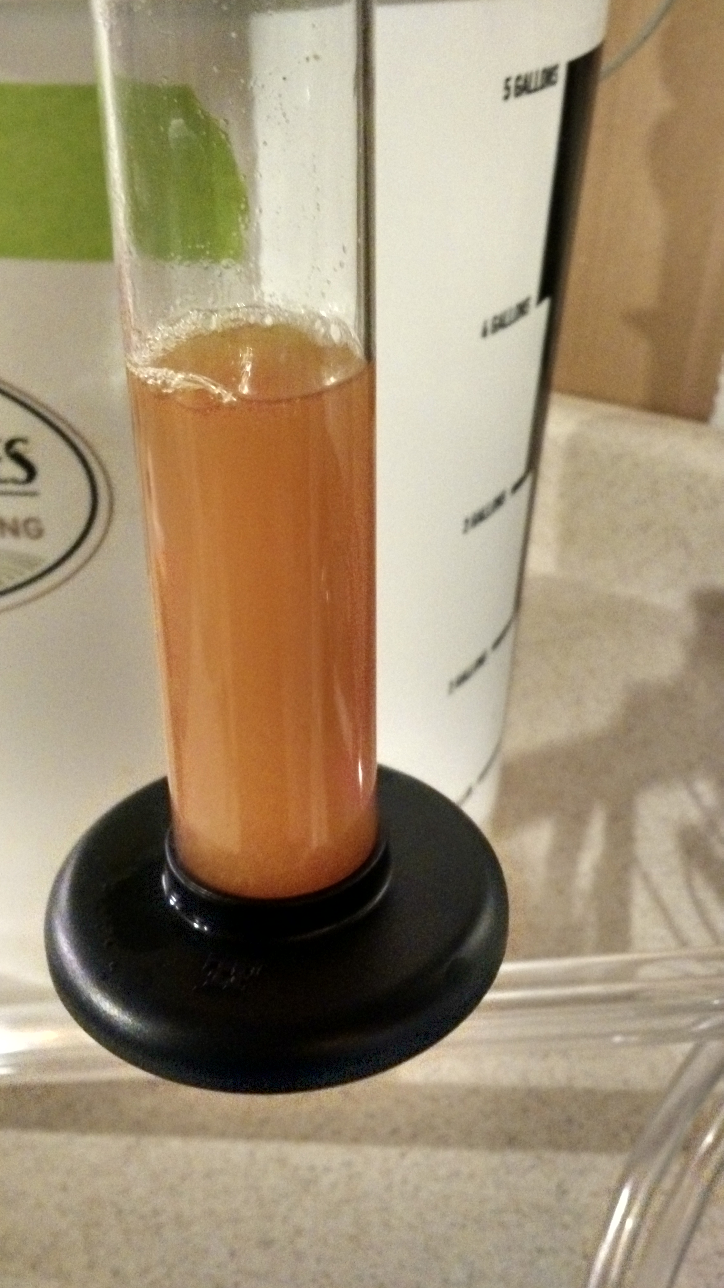
The color is lighter, probably because I added the DME near the end, but I was still looking for lighter. I’ll also want to get it clearer.